Instrument Cluster Description and operation
Description
Communication Network Diagram
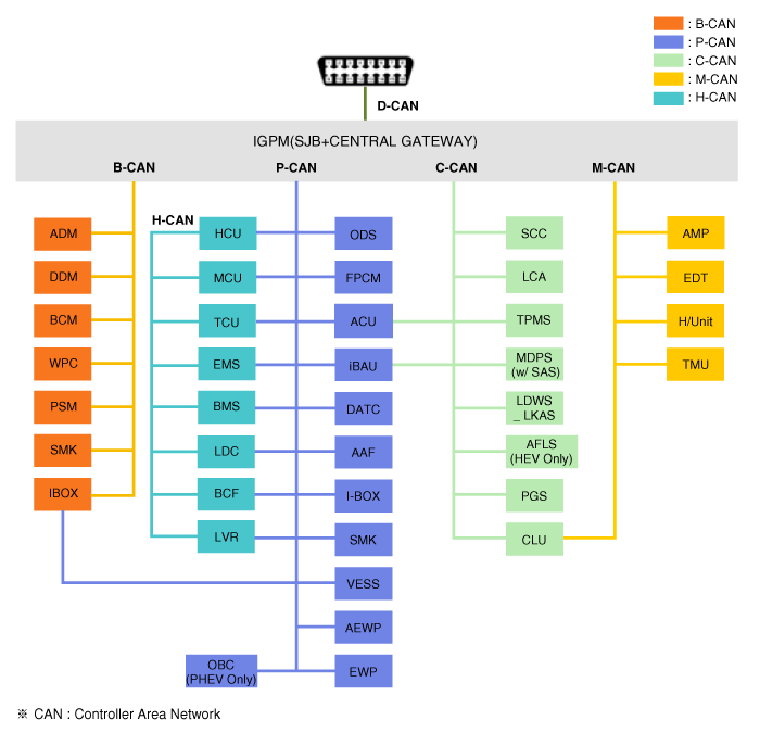
| Abbreviation | Expalnation |
| AAF | Active Air Flap |
| ACU | Airbag Control Unit |
| AEB | Autonomous Emergency Braking |
| AHB | Active Hybrid Brake System |
| AMP | Amplifier |
| AVN | Head Unit (Audio / AVN) |
| B_CAN | Body Controller Area Network |
| BCM | Body Control Module |
| BMS | Battery Management System |
| BSD | Blind Spot Detection |
| C_CAN | Chassis Controller Area Network |
| CARMERA | Rear View Carmera |
| CLU | Cluster Module |
| DATC | Dual Automatic Temp Control |
| FPCM | Fuel Pump Control Module |
| HPCU | Hybrid Power Unit |
| IGPM | Intergrated Gateway & Power control Module |
| LDWS | Lane Departure Warning System |
| M_CAN | Multi media Controller Area Network |
| MDPS | Motor Driven Power Steering |
| P_CAN | Powertrain Controller Area Network |
| PAS | Parking Assist System |
| OCS | Occupant Classipication Sensor |
| SJB | Smart Junction Block |
| SMK | Smart Key Unit |
| TCM(DCT) | Double Clutch Transmission Unit |
| VESS | Virtual Engine Sound System |
Cluster Variant Coding
As we have more options (ESC, MDPS etc.) in the car, the dashboard now has more information to display depending on the chosen options.
For this reason, we need to learn which options the vehicle has when replacing the dashboard.
To address this issue, a course of learning based on the option required for the vehicle when replacing the dashboard should be carried out.
This is called Variant Coding.
Function
High speed CAN communication (C-CAN)
Custom Function : car seats linked to getting on/off motion, Welcome Light
LDWS : Lane Departure Warning System
SPAS: Smart Parking Assist System
Low speed CAN communication (M-CAN)
AV : Audio / Video Multimedia information Display
TBT : Turn By Turn Navigation Information Display
Sound output
Various alarms and sound effects are issued through the external speakers connected to the dashboard.
If External AMP is applied, the directional alarm is outputted through the amp.
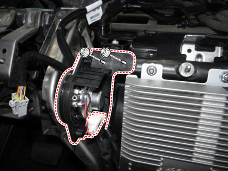
Sound Description and function (CAN data receiver) Welcome Welcome (Key out and door open/closed state checked by BCM Goodbye Goodbye (Cluster) Door Open warning Key reminder warning (BCM), Vehicle speed is 5 km/h or below & IGN switch is ACCor IGN or engine start & when vehicle speed is below 5 km/h or when the driverside door is opened Seat belt warning Driver seat belt warning (BCM) PAS System warning PAS sensor fault warning (BCM) Gear R PAS warning when shift gear R (BCM and SPAS) Parking Brake Parking brake warning (BCM) Start button SSB button warning (SMK) Rheostat light information Rheostat warning when select the max or min degree (Cluster) Smart Key departure Smart key out warning (SMK) Non smart key warning (SMK) conventional cruise Change the conventional cruise Turn signal lamp (Tick) Turn signal lamp warning (BCM) Turn signal lamp (Tock) Turn signal lamp warning (BCM) Smart key battery low voltage Warning when driver push the SSB button with low voltage battery smart key (SMK) EPB warning Warning when change from Auto Hold to EPB lock (EPB) Coolant temperature alarm When the engine temperature is over 120 °C User Setting Mode (USM)
Setting can be changed by using switchs (Menu, UP, Down and OK button). There are many items (for example, In/Out Seat Synchronization, In/Out Steering Wheel Synchronization, Auto Door Lock, Auto Door Lock Deactivate, Head Lamp Escort, Welcome Light, Welcome Sound, One Touch Turn Signal, Average Fuel Consumption Auto Reset, Brightness, and Content Setup) that can be set and customized. The signal flow during setting is as follows.
UMS settings are set, they are transmitted to BCM.
BCM transmits the settings via B-CAN to the relevant modules.
The module completes setting and transmits the modified setting to BCM.
BCM transmits the final settings via C-CAN to the cluster.
Hybrid Mian Features
ECO and power guage

It displays the degree of economic driving by identifying the status of a driver's operation, depending on a vehicle's driving conditions (e.g., required power, system efficiency and charging).
It leads to economic driving by informing the driver of the optimal driving conditions depending on the vehicle's conditions.
It displays that ECO guide and power segment will operate during driving, and also indicates the state of regenerative braking when a charge zone is instructed while driving.
SOC(State of Charge) guage
It displays the amount of charge of high-voltage battery.
It displays the charged amount of SOC received from BMS module on the digital gauge in the instrument cluster (as follows).
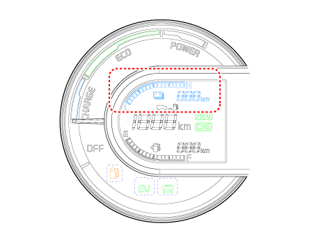
No. SOC(%) No. SOC(%) 0 ~ 19.5 9 55.5 ~ 60 1 20 ~ 23 10 60.5 ~ 65 2 23.5 ~ 26 11 65.5 ~ 70 3 26.5 ~ 30 12 70.5 ~ 75 4 30.5 ~ 35 13 75.5 ~ 80 5 35.5 ~ 39.5 14 80.5 ~ 85 6 40 ~ 44.5 15 85.5 ~ 92 7 45 ~ 50 16 92.5 ~ 95 8 50.5 ~ 55 Energy Flow
It displays graphical energy flow of an HEV vehicle to inform the driver of the vehicle information.
It leads to economic driving by showing the energy flow diagram by means of intuitive images.
HCU module receives operation mode CAN signals to implement any relevant animation.
No. Definition Graphic Remark 1 Vehicle stopped 
- 2 Vehicle mode driven only by motor 
Battery > Wheels 3 Vehicle mode driven by motor and engine 
Batteries > Wheels
Engine > Wheels4 Vehicle mode driven only by engine 
Engine > Wheels 5 Engine stops at the high-voltage battery charge state. 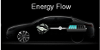
Engine > Batteries 6 Due to the high voltage battery charging regenerative braking. 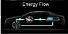
Wheels > Batteries 7 Engine Friction braking conditions using a vehicle. 
Wheels > Engine 8 Engine amount of secondary high-voltage battery charging while driving 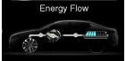
Engine > Wheels
Engine > Batteries9 Vehicle mode in which motor engine is used to recharge the battery 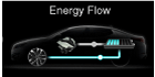
Engine > Batteries
Batteries > Wheels10 Engine Generation / Regeneration 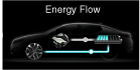
Engine > Batteries
Wheels > Batteries11 Engine Brake / Regeneration 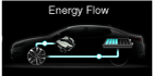
Wheels > Engine
Wheels > Batteries