Instrument Cluster Repair procedures
Removal
Instrument Cluster
Disconnect the negative (-) battery terminal.
Remove the cluster fascia panel.
(Refer to Body - "Cluster Fascia Panel")
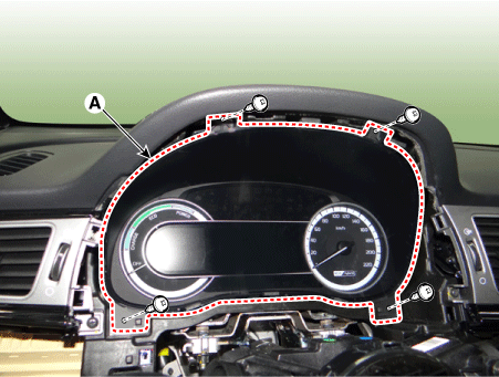
Separate the instrument cluster (A) after loosening the mounting screws.
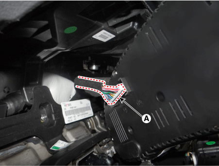
Remover the instrument cluster after disconnecting the cluster connector (A).
Instrument Cluster Speaker
Disconnect the negative (-) battery terminal.
Remove the crash pad center lower panel.
(Refer to Body - "Crash Pad Center Panel")
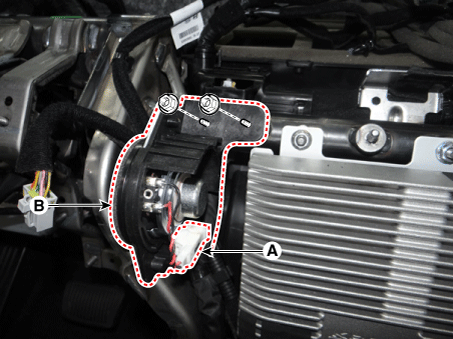
Disconnect the instrument cluster speaker connector (A).
Remove the instrument cluster speaker (B) after loosening the mounting nuts.
Installation
Instrument Cluster
Install the cluster after connect the cluster connectors.
Install the cluster fascia panel.
Connect the negative (-) battery terminal.
Instrument Cluster Speaker
Install the cluster speaker after connect the cluster connectors.
Install the crash pad center lower panel.
Connect the negative (-) battery terminal.
Inspection
Check point (Warning indicator)
NO Ref Symbol Name Color Signal Input Signal Control Check Point 1 
Turnsignal (Left) Green CAN BCM
(Gateway)Multifunction Switch
BCM
CAN Failure
2 
Turnsignal (Right) Green CAN BCM
(Gateway)Multifunction Switch
BCM
CAN Failure
3 
Tail Lamp Green CAN BCM
(Gateway)Multifunction Switch
BCM
CAN Failure
4 
Front
Fog LampGreen CAN BCM
(Gateway)Multifunction Switch
BCM
CAN Failure
5 
Rear Fog Lamp Yellow CAN BCM
(Gateway)Multifunction Switch
BCM
CAN Failure
6 
Low Beam Green CAN BCM
(Gateway)Multifunction Switch
BCM
CAN Failure
7 
High Beam Blue CAN BCM
(Gateway)Multifunction Switch
BCM
CAN Failure
8 
Master Symbol Yellow CAN BSD BSD System
CAN Failure
TPMS TPMS System
CAN Failure
BCM External lamps
BCM
CAN Failure
Hard-wired Fuel Sender Fuel Sendar Failure
Wiring Failure
Low Washer Whasher fluid lever sensor
Wiring Failure
Digital Input Reminders when service checks 9 
Battery Charge Red CAN ECM Charging System
CAN Failure
10 
Oil Pressure Red Hard-wired ECM ECM System
Hard-wired
CAN Failure
11 
Check Engine Yellow CAN ECM ECM System
CAN Failure
12 
Immobilizer Yellow CAN BCM
(Gateway)SMK System
BCM
CAN Failure
Hard-wired
13 
Parking Brake
Brake Fluid
EBD
EPBRed CAN BCM
(Gateway)
EBD
EPB
ABS
TCSBCM
ABS System
EPB System
CAN Failure
Parking Brake Switch
Brake Oil Lever Sensor
14 
ABS Yellow CAN ABS ABS System
CAN Failure
15 
ESC Yellow CAN TCS ABS System
CAN Failure
16 
ESC Off Yellow CAN TCS ABS System
CAN Failure
17 
Seat Belt Red CAN BCM
(Gateway)BCM
CAN Failure
18 
Airbag Red CAN SRSCM SRSCM System
CAN Failure
19 
EPS
(MDPS)Red CAN MDPS MDPS Unit System
MDPS Motor
CAN Failure
20 
TPMS Yellow CAN TPMS TPMS System
TPMS Sensor
CAN Failure
21 
LDWS Green
Yellow
WhiteCAN LDWS LDWS System
CAN Failure
22 
Fuel Warning Yellow Direct
(Micom)Fuel Segment Fuel Sendar Failure
Wiring Failure
23 
ECO Green Hard-wired ECO mode ECM System
CAN Failure
24 
SPORT Yellow Hard-wired SPORT mode ECM System
CAN Failure
25 
CRUISE Green CAN ECM ECM System
CAN Failure
26 
SET Green CAN ECM ECM System
CAN Failure
27 
Over speed Yellow CAN ECM ECM
CAN Failure
28 
AEB Yellow CAN SCC AEB System
CAN Failure
29 
Cooling water
temperatureRed CAN EMS EMS System
CAN Failure
30 
Service Yellow CAN HCU
MCU
GCU
BMS
LDC
TCU
OBCHCU System
MCU System
GCU System
BMS System
LDC System
TCU System
OBC System
CAN Failure
31 
Ready Green CAN HCU HCU System
CAN Failure
32 
EV mode Green CAN HCU HCU System
CAN Failure
33 
Regenerative
Brahing System
(RBS)Yellow CAN HCU HCU System
CAN Failure
Check point (Gauge)
NO Name Signal Input Signal Control
(Unit/Sensor)Check Point 1 Speedometer C-CAN ABS/ESC 1. ABS System
2. CAN Line failure2 Tachometer C-CAN ECM 1. ECM
2. CAN Line failure3 Cooling water temperature C-CAN ECM 1. ECM
2. CAN Line failure4 Fuel Hardwire Fuel Sander 1. Fuel sender failure
2. Wiring failure
Diagnosis with KDS/GDS
In the body electrical system, failure can be quickly diagnosed by using the vehicle diagnostic system (KDS/GDS).
The diagnostic system (KDS/GDS) provides the following information.
Self diagnosis : Checking failure and code number (DTC)
Current data : Checking the system input/output data state
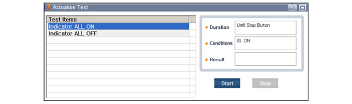
Actuation test : Checking the system operation condition
Additional function : Controlling other features including system option setting and zero point adjustment
Select the 'Car model' and the 'Cluster Module (CLU)' to be checked in order to check the vehicle with the tester
Select the 'Current Data' menu to search the current state of the input/output data.

To forcibly actuate the input value of the module to be checked, select option 'Actuation Test'
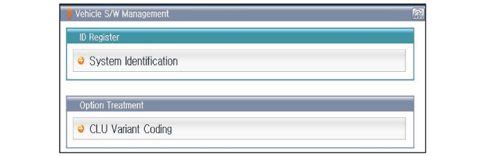
CLU Variant Coding
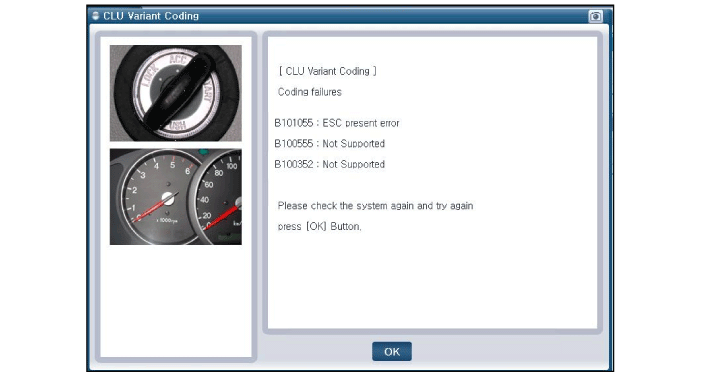
After replacing the cluster with a new one, must be performed the “Variant Coding” procedure.
Connect the cable of KDS/GDS to the data link connector in driver side crash pad lower panel, turn the power on KDS/GDS.
Select model and "BCM".
Select Variant coding mode to perform.
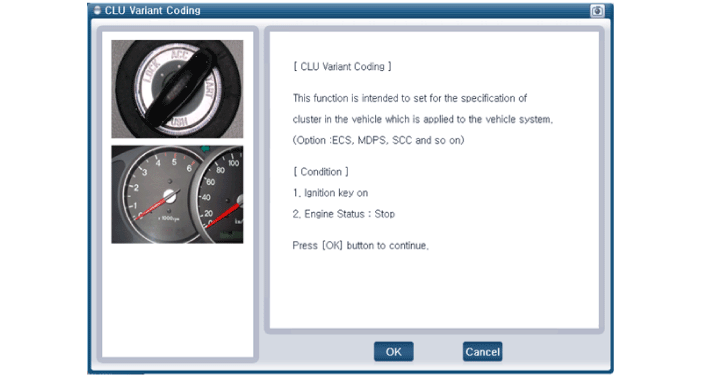

If the trouble codes occurred when performing variant coding, try the CLU variant coding again after checking the installation status of CLU system.