Timing Chain Cover Repair procedures
Removal
Shut off the high voltage circuit.
(Refer to Engine Mechanical System - “High Voltage Shut off Procedure”)
Remove the air cleaner.
(Refer to Intake and Exhaust System - "Air Cleaner")
Remove the RH front wheel.
(Refer to Suspension System - "Wheel")
Remove the engine room under cover.
(Refer to Engine and Transaxle Assembly - "Engine Room Under Cover")
Drain the engine oil.
(Refer to Lubrication System - "Engine Oil")
Drain the engine coolant.
(Refer to Cooling System - "Coolant")
Remove the drive belt.
(Refer to Drive Belt System - "Drive Belt")
Remove the drive belt tensioner.
(Refer to Drive Belt System - "Drive Belt Tensioner")
Remove the idler.
(Refer to Drive Belt System - "Idler")
Remove the crankshaft damper pulley.
(Refer to Drive Belt System - "Crankshaft Damper Pulley")
Remove the water pump.
(Refer to Cooling System - "Water Pump")
Remove the cylinder head cover.
(Refer to Cylinder Head Assembly - "Cylinder Head Cover")
Remove the oil pan.
(Refer to Lubrication System - "Oil Pan")
Remove the engine mounting support bracket.
Install the jack under the edge of the ladder frame to support the engine.
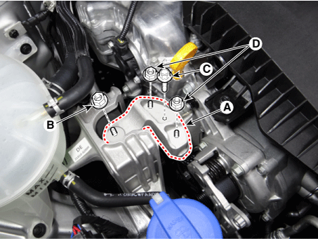
Remove the engine mounting support bracket (A).
Tightening torque
Nut (B) :
88.3 - 108 N·m
Bolt (C) and nuts (D) :
58.8 - 74 N·m
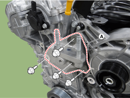
Remove the engine support bracket (A).
Tightening torque : 39.2 - 44 N·m
Remove the oil level gauge.
(Refer to Lubrication System - "Oil Level Gauge & Pipe")
Remove the variable force solenoid (VFS) valve (A).

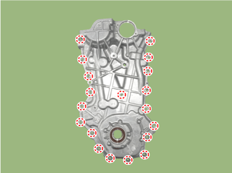
Remove the timing chain cover (A).

Installation
Install the timing chain cover (A).
Using a gasket scraper, remove all the old packing material from the gasket surfaces.
The sealant locations on the chain cover and the counter parts (cam carrier, cylinder head, cylinder block, and lower crankcase) must be free of harmful foreign materials, oil, dust and moisture. Spray cleaner on the surface and wipe with a clean duster.
Before assembling the timing chain cover, liquid sealant should be applied on the gap between cam carrier, cylinder head and cylinder block.
Bead width : 3.0 - 5.0 mm (0.11 - 0.20 in.)
Sealant : Threebond 1217H or equivalent
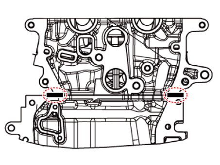
Install the new O-ring (A).

After applying liquid sealant on the timing chain cover, assemble the cover within 5 minutes of applying sealant. Continuous bead of sealant should be applied to prevent any path from oil leakage.
Bead width :
Whole section: 2.5 - 3.5 mm (0.10 - 0.14 in.)
Section : 3.5 - 4.5 mm (0.14 - 0.18 in.)
Sealant : Threebond 1217H or equivalent
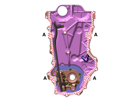
Install the timing chain cover. The dowel pins on the cylinder block and holes on the timing chain cover should be used as a reference for assembling the timing chain cover to the exact position.
Tightening torque : 18.6 - 24 N·m
Install the variable force solenoid (VFS) valve (A).
Tightening torque : 9.8 - 11,8 N·m
Replace the front oil seal if necessary.
(Refer to Timing System - "Front Oil Seal")
Install the remaining parts in the reverse order of removal.
Connect the high voltage circuit.
(Refer to Engine Mechanical System - “High Voltage Shut off Procedure”)
Add all the necessary fluids and check for leaks. Connect KDS/GDS. Check for codes, note, and clear. Recheck.