A/C Unit Disassembly/Assembly
1. Disassemble in the order indicated in the table.
CAUTION:If a non-specified grease is used, it may result in abnormal noise or improper operation of the links. Apply only the specified grease to each link.
2. Assemble in the reverse order of disassembly.
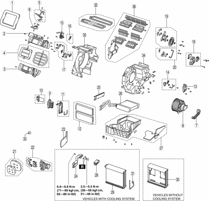
X: Applicable—: Not applicable
Step |
Part name |
Disassembly/assembly of main parts |
||
Heater core |
Evaporator temperature sensor |
Evaporator |
||
1 |
Adhesive polyurethane (1) |
- |
- |
- |
2 |
Blower case (1) |
- |
- |
- |
3 |
Blower case (2) |
- |
- |
- |
4 |
Air intake door |
- |
- |
- |
5 |
Air intake link set |
- |
- |
- |
6 |
Air intake actuator |
- |
- |
- |
7 |
Blower motor pipe |
- |
- |
- |
8 |
Blower motor |
- |
- |
- |
9 |
Power MOS FET (Full-auto air conditioner) |
- |
- |
- |
10 |
Resistor (Manual air conditioner) |
- |
- |
- |
11 |
Plate |
- |
X |
X |
12 |
Air filter |
- |
X |
X |
13 |
Driver-side air mix actuator (Full-auto air conditioner) |
- |
- |
- |
14 |
Driver-side air mix link set (Full-auto air conditioner) |
- |
- |
- |
15 |
Passenger-side air mix actuator (Full-auto air conditioner) |
- |
- |
- |
16 |
Passenger-side air mix link set (Full-auto air conditioner) |
- |
- |
- |
17 |
Air mix link set (Manual air conditioner) |
- |
- |
- |
18 |
Airflow mode actuator (Full-auto air conditioner) |
- |
- |
- |
19 |
Airflow mode link set |
- |
- |
- |
20 |
Airflow mode link set (Manual air conditioner) |
- |
- |
- |
21 |
Polyurethane foam (1) |
X |
X |
X |
22 |
Plate cover |
X |
X |
X |
23 |
Adhesive polyurethane (2) (See Adhesive Polyurethane (2) Assembly Note.) |
X |
X |
X |
24 |
Evaporator pipe |
X |
X |
X |
25 |
Cover |
X |
X |
X |
26 |
Heater core |
- |
X |
X |
27 |
A/C case (1) |
- |
X |
X |
28 |
Expansion valve |
- |
X |
X |
29 |
Evaporator |
- |
- |
- |
30 |
A/C case (2) |
- |
- |
- |
31 |
Evaporator temperature sensor . |
- |
- |
- |
32 |
Polyurethane foam (2) |
- |
- |
- |
33 |
Bolt |
- |
- |
- |
34 |
A/C case (3) |
- |
- |
X |
35 |
A/C case (4) |
- |
- |
X |
36 |
Door damper |
- |
- |
- |
Evaporator Temperature Sensor Assembly Note
1. Assemble the evaporator temperature sensor as shown in the figure.
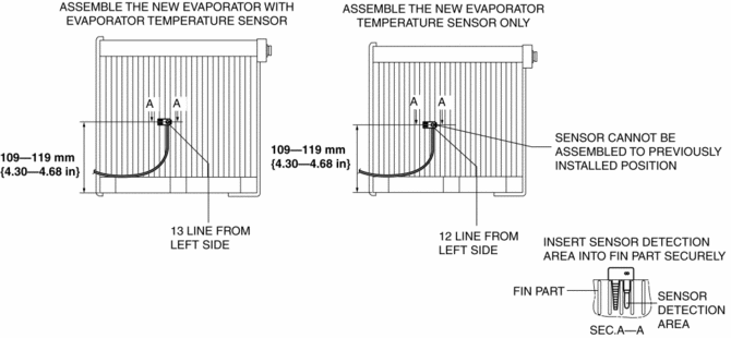
CAUTION:
When installing the evaporator temperature sensor without replacing the evaporator, assemble the evaporator temperature sensor with the installation position slid to the left of the previous position by 1 line. If the evaporator temperature sensor is assembled to the previously installed position, it may not function due to poor contact of the fin surface with the sensor detection area caused by fin deformation.
Replace the evaporator in which the evaporator temperature sensor cannot be correctly positioned.
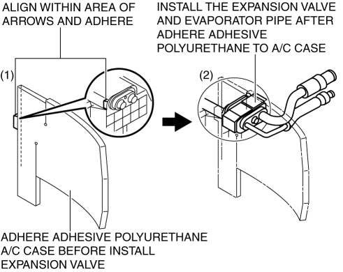
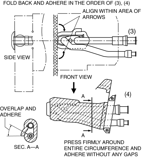
1. Assemble the adhesive polyurethane as shown in the figure.
Test yourself
A quick Mazda 3 quiz: every answer comes with an explanation and a link to the manual page.