Climate Control Unit Inspection [Manual Air Conditioner]
1. Remove the climate control unit with the connector connected..
2. Switch the ignition to ON.
3. Connect the negative (-) lead of the tester to the body ground.
4. By inserting the positive (+) lead of the tester into the climate control unit connector, measure the voltage according to the terminal voltage table.
If there is any malfunction, inspect the parts under “Inspection item(s)”.
If the parts under “Inspection item(s)” are normal, replace the climate control unit.
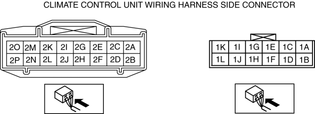
Terminal Voltage Table (Reference)
Terminal |
Signal name |
Connected to |
Measurement condition |
Voltage (V) |
Inspection item(s) |
1A |
― |
― |
― |
― |
― |
1B |
Motor operation |
Air intake actuator |
Switched to RECIRCULATE |
B+ |
|
Switched to FRESH |
1.0 or less |
||||
1C |
Evaporator temperature sensor input |
Evaporator temperature sensor |
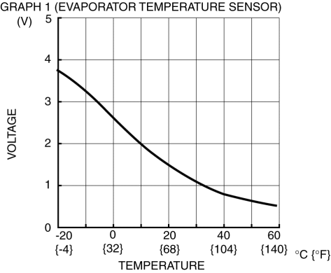
Compared with temperature detected by evaporator temperature sensor |
Refer to graph 1 |
|
1D |
― |
― |
― |
― |
― |
1E |
― |
― |
― |
― |
― |
1F |
Motor operation |
Air intake actuator |
Switched to RECIRCULATE |
1.0 or less |
|
Switched to FRESH |
B+ |
||||
1G |
Sensor GND |
|
Under any condition |
1.0 or less |
|
1H*1 |
+5 V |
Refrigerant pressure sensor |
Switch the ignition to ON |
5 |
|
Switch the ignition to Off |
1.0 or less |
||||
1I |
Ground |
Body ground |
Under any condition |
1.0 or less |
|
1J |
― |
― |
― |
― |
― |
1K*2 |
Fan switch position |
Fan switch |
Fan switch position 0, 1 and 2 |
B+ |
|
Fan switch position 3 and 4 |
1.0 or less |
||||
1L |
Blower fan ON/OFF signal |
Fan switch |
Fan stopped |
B+ |
|
Fan on |
1.0 or less |
||||
2A |
Illumination (-) |
Instrument cluster |
Headlight ON and panel light control MAX |
2.0 |
|
Headlight ON and panel light control MIN |
9.65 |
||||
2B |
B+ |
ROOM 15 A fuse |
Under any condition |
B+ |
|
2C |
― |
― |
― |
― |
― |
2D |
LIN |
BCM |
Because this terminal is for communication, good/no good judgement by terminal voltage is not possible. |
|
|
2E |
― |
― |
― |
― |
― |
2F |
TNS signal |
TNS relay |
TNS OFF |
1.0 or less |
|
TNS ON |
B+ |
||||
2G |
― |
― |
― |
― |
― |
2H |
IG2 |
HEATER 10 A fuse |
IG SW ON |
B+ |
|
IG SW LOCK |
1.0 or less |
||||
2I |
― |
― |
― |
― |
― |
2J*1 |
Refrigerant pressure sensor signal |
Refrigerant pressure sensor |
Compared with temperature detected by refrigerant pressure sensor |
(See REFRIGERANT PRESSURE SENSOR INSPECTION [MANUAL AIR CONDITIONER].) |
|
2K |
Rear window defroster indicator |
BCM |
Rear window defroster OFF |
11.12 |
|
Rear window defroster ON |
1.0 or less |
||||
2L |
― |
― |
― |
― |
― |
2M |
― |
― |
― |
― |
― |
2N |
― |
― |
― |
― |
― |
2O |
Rear window defroster signal |
BCM |
While pressed rear window defroster switch |
1.0 or less |
|
Released rear window defroster switch |
4.7 |
||||
2P |
A/C signal |
Instrument cluster |
A/C ON |
1.0 or less |
|
A/C OFF |
4.8 |
||||
*1 MZR 2.0, MZR 2.5 *2 SKYACTIV-G 2.0
Test yourself
A quick Mazda 3 quiz: every answer comes with an explanation and a link to the manual page.