Starter Cut Relay Inspection [MTX]
1. Disconnect the negative battery cable.
2. Remove the following parts:
a. Front scuff plate (LH).
b. Front side trim (LH).
c. Side wall.
d. Console.
3. Set the bonnet release lever out of the way..
4. Remove the lower panel..
5. Remove the starter cut relay with the connector connected..
6. Connect the negative battery cable..
7. Measure the voltage at each terminal is as indicated in the terminal voltage tables.
If the voltage or continuity is not as specified in the terminal voltage table, inspect the parts under “Inspection item (s)”.
If the system does not work properly even though the parts or related wiring harnesses do not have any malfunction, replace the starter cut relay.

Terminal |
Signal name |
Connected to |
Measurement condition |
Voltage (V) |
Inspection item (s) |
||
A |
Power supply |
Starter relay |
Switch the ignitions to off |
Clutch pedal is not depressed |
Wave pattern 1 (See Pattern 1.) |
|
|
Clutch pedal is depressed |
Wave pattern 2 (See Pattern 2.) |
||||||
Switch the ignitions to ON |
Clutch pedal is not depressed |
B+ |
|||||
Clutch pedal is depressed |
1.0 or less |
|
|||||
D |
Starter cut relay output signal |
|
Switch the ignitions to off |
Clutch pedal is not depressed |
Wave pattern 2 (See Pattern 2.) |
|
|
Clutch pedal is depressed |
1.0 or less |
||||||
H |
Starter interlock switch |
Starter interlock switch |
Switch the ignitions to ON |
Clutch pedal is not depressed |
B+ |
|
|
Clutch pedal is depressed |
1.0 or less |
||||||
I |
IG 1 |
Stop 15 A fuse |
Switch the ignition to ON |
B+ |
|
||
Switch the ignition to off |
1.0 or less |
||||||
Generated pulse (reference) Pattern 1
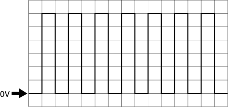
Terminal: A (+) ↔ body ground (-)
Oscilloscope setting: 2 V/DIV (Y), 100 ms/DIV (X), DC range
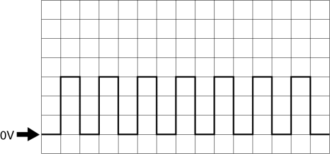
Terminal:
A (+) ↔ body ground (-)
D (+) ↔ body ground (-)
Oscilloscope setting: 2 V/DIV (Y), 100 ms/DIV (X), DC range
Test yourself
A quick Mazda 3 quiz: every answer comes with an explanation and a link to the manual page.