Duct and grille
Exploded View
FRONT
LHD models
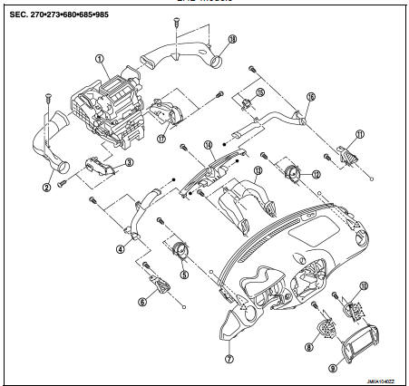
1. A/C unit assembly 2. Side ventilator duct LH 3. Foot duct LH
4. Side defroster nozzle LH 5. Side ventilator grille LH 6. Side defroster grille LH 7. Instrument panel assembly 8. Center ventilator grille LH 9. Cluster lid C
10. Center ventilator grille RH 11. Side defroster grille RH 12. Side ventilator grille RH 13. Center ventilator duct 14. Front defroster nozzle 15. Instrument panel bracket 16. Side defroster nozzle RH 17. Foot duct RH
18. Side ventilator duct RH
 : Pawl
REAR

1. A/C unit assembly 2. Rear heater duct 1 LH* 3. Rear heater duct 2 LH* 4. Rear heater duct 3 LH* 5. Rear heater duct 1 RH* 6. Rear heater duct 2 RH* 7. Rear heater duct 3 RH*
: Pawl
*: Only LHD models for cold areas.
FRONT
RHD models
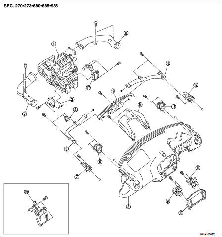
1. A/C unit assembly 2. Side ventilator duct LH 3. Foot duct LH
4. Instrument panel bracket 5. Side defroster nozzle LH 6. Side ventilator grille LH 7. Side defroster grille LH 8. Instrument panel assembly 9. Center ventilator grille LH 10. Cluster lid C
11. Center ventilator grille RH 12. Side defroster grille RH 13. Side ventilator grille RH 14. Center ventilator duct 15. Front defroster nozzle 16. Side defroster nozzle RH 17. Foot duct RH
18. Side ventilator duct RH 19. Foot duct RH (2WD models)
: Pawl
Center ventilator grille
CENTER VENTILATOR GRILLE : Removal and Installation
REMOVAL
1. Remove cluster lid C. Refer to IP-13, "Removal and Installation".2. Remove fixing screws (A).

3. Disengage fixing pawls (A), and then remove center ventilator grille from cluster lid C.
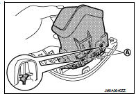
INSTALLATION Install in the reverse order of removal.
SIDE DEFROSTER NOZZLE : Removal and Installation
REMOVAL
Driver side1. Remove instrument panel assembly. Refer to IP-13, "Removal and Installation".
2. Remove fixing screws (A), and then remove side defroster nozzle from instrument panel assembly.

Passenger side
1. Remove instrument panel assembly. Refer to IP-13, "Removal and Installation". 2. Remove fixing screws (A), and then remove instrument panel bracket (1).
3. Remove fixing screw (B), and then remove side defroster nozzle (2) from instrument panel assembly.
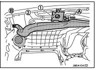
INSTALLATION
Install in the reverse order of removal.
SIDE VENTILATOR GRILLE : Removal and Installation
REMOVAL
1. Remove instrument panel assembly. Refer to IP-13, "Removal and Installation".2. Remove fixing screws (A), and then remove side ventilator grille from instrument panel assembly.
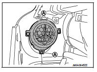
INSTALLATION
Install in the reverse order of removal.
SIDE DEFROSTER GRILLE : Removal and Installation
REMOVAL
1. Remove instrument panel assembly. Refer to IP-13, "Removal and Installation". 2. Remove side defroster nozzle. Refer to VTL-10, "SIDE DEFROSTER NOZZLE : Removal and Installation".3. Remove fixing screw (A) and disengage fixing pawl (B), and then remove side defroster grille from instrument panel assembly.
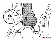
INSTALLATION
Install in the reverse order of removal
Front defroster nozzle
FRONT DEFROSTER NOZZLE : Removal and Installation
REMOVAL
1. Remove instrument panel assembly. Refer to IP-13, "Removal and Installation". 2. Remove side defroster nozzle. Refer to VTL-10, "SIDE DEFROSTER NOZZLE : Removal and Installation".3. Remove fixing screw (A), and then remove front defroster nozzle from instrument panel assembly.
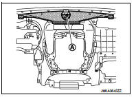
INSTALLATION
Install in the reverse order of removal.
Center ventilator duct
CENTER VENTILATOR DUCT : Removal and Installation
REMOVAL
1. Remove instrument panel assembly. Refer to IP-13, "Removal and Installation". 2. Remove side defroster nozzle (LH and RH). Refer to VTL-10, "SIDE DEFROSTER NOZZLE : Removal and Installation". 3. Remove front defroster nozzle. Refer to VTL-11, "FRONT DEFROSTER NOZZLE : Removal and Installation".4. Remove fixing screws (A), and then remove center ventilator duct from instrument panel assembly.
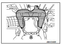
INSTALLATION
Install in the reverse order of removal.
Side ventilator duct : Removal and Installation
REMOVAL
1. Remove instrument panel assembly. Refer to IP-13, "Removal and Installation".2. Remove fixing screws (A), and then remove side ventilator duct (LH and RH) from the vehicle.
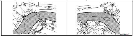
INSTALLATION
Install in the reverse order of removal.
Rear heater duct 1 : Removal and Installation
REMOVAL
1. Remove center console assembly. Refer to IP-23, "Removal and Installation".2. Disengage fixing pawls, and then remove rear heater duct 1 (LH and RH) from A/C unit assembly.
 : Pawl
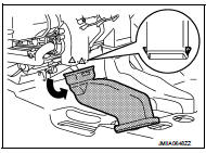
INSTALLATION
Install in the reverse order of removal.
Rear heater duct 2 : Removal and Installation
REMOVAL
1. Remove center console assembly. Refer to IP-23, "Removal and Installation". 2. Remove front seat assmbly. Refer to SE-19, "Removal and Installation". 3. Remove front kicking plate inner and rear kicking plate inner. Refer to INT-19, "KICKING PLATE INNER : Removal and Installation". 4. Remove center pillar lower garnish. Refer to INT-20, "CENTER PILLAR LOWER GARNISH : Removal and Installation". 5. Remove dash side finisher. Refer to INT-20, "DASH SIDE FINISHER : Removal and Installation".6. Remove rear heater duct 2.
• Peel off floor carpet (1).• Remove rear heater duct 3 (2) from rear heater duct 2 (3).
 : Vehicle front
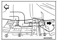
• Remove front floor spacer, and then remove rear heater duct 2 (2) from rear heater duct 1 (1).
 : Vehicle front
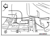
INSTALLATION
Install in the reverse order of removal.
Foot duct : Removal and Installation
REMOVAL
Driver side1. Remove instrument lower panel. Refer to IP-13, "Removal and Installation".
2. Remove foot duct (LH/RH).
• Disconnect harness connector. • Remove harness connector mounting clamp.• Remove fixing screws, and then remove foot duct (LH/RH).
Passenger side1. Remove glove box assembly. Refer to IP-13, "Removal and Installation".
2. Remove fixing screws, and then remove foot duct (LH/RH).
INSTALLATION
Install in the reverse order of removal.