Front stabilizer
Exploded View
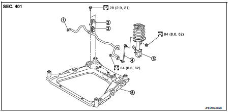
1. Stabilizer bar
2. Stabilizer clamp
3. Stabilizer bushing
4. Stabilizer connecting rod 5. Strut assembly
6. Front suspension member
 : N·m (kg-m, ft-lb)
Removal and Installation
REMOVAL
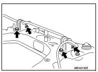
1. Remove tires. Refer to WT-7, "Removal and Installation". 2. Remove front suspension member. Refer to FSU-18, "Removal and Installation". 3. Remove stabilizer connecting rod. 4. Remove mounting bolts ( ) of
stabilizer clamp, and then remove stabilizer clamp and stabilizer bushing from front suspension member. 5. Remove stabilizer bar.
6. Perform inspection after removal. Refer to FSU-17, "Inspection".
INSTALLATION
Note the following, and install in the reverse order of removal.
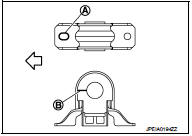
• Install stabilizer clamp and stabilizer bush with notch (A) and slit (B) faced forward of the vehicle ( ).
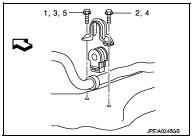
• To install stabilizer clamp mounting bolt, follow the tightening method and the numerical order shown below:
Manual tightening : 1 Temporary tightening : 2 → 3 Final tightening (Specified torque) : 4 → 5
 : Vehicle front
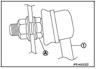
• To install stabilizer connecting rod (1), tighten the mounting nut with the hexagonal part (A) on the stabilizer connecting rod side fixed. • Perform final tightening of bolts and nuts at the vehicle installation position (rubber bushing), under unladen conditions with tires on level ground.
• Perform inspection after installation. Refer to FSU-14, "Inspection".
Inspection
INSPECTION AFTER REMOVAL
Check stabilizer bar, stabilizer connecting rod, stabilizer bushing and stabilizer clamp for deformation, cracks or damage. Replace it if necessary.
INSPECTION AFTER INSTALLATION
Check wheel alignment. Refer to FSU-7, "Inspection".