Navigation Receiver
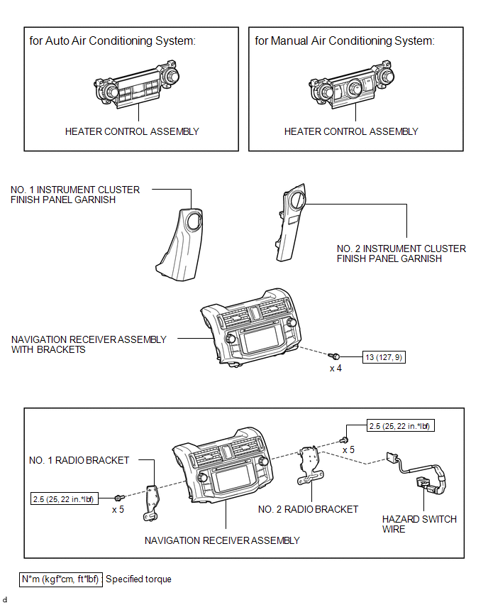
Removal REMOVAL PROCEDURE
1. DISCONNECT CABLE FROM NEGATIVE BATTERY TERMINAL
CAUTION:
Wait at least 90 seconds after disconnecting the cable from the negative (-) battery terminal to disable the SRS system.
NOTICE:
When disconnecting the cable, some systems need to be initialized after the cable is reconnected (See page  ).
2. REMOVE NO. 1 INSTRUMENT CLUSTER FINISH PANEL GARNISH
3. REMOVE NO. 2 INSTRUMENT CLUSTER FINISH PANEL GARNISH
4. REMOVE HEATER CONTROL ASSEMBLY
5. REMOVE NAVIGATION RECEIVER ASSEMBLY WITH BRACKETS
(a) Remove the 4 bolts. |
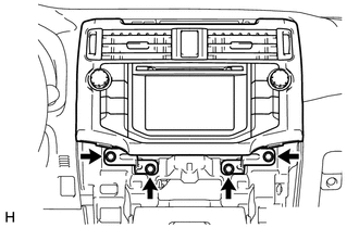 |
(b) Pull the navigation receiver assembly with brackets as shown in the illustration to detach the 6 claws on the backside of the navigation receiver assembly with brackets. |
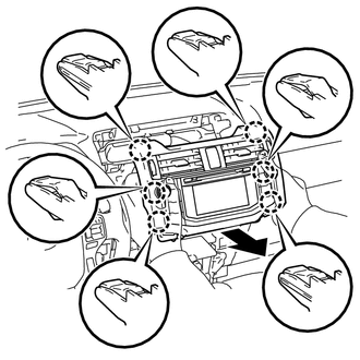 |
(c) Disconnect each connector to remove the navigation receiver assembly with brackets.
6. REMOVE HAZARD SWITCH WIRE
(a) Detach the 2 clamps. |
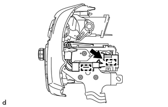 |
(b) Disconnect the connector to remove the hazard switch wire.
7. REMOVE NO. 1 RADIO BRACKET
(a) Remove the 5 screws and No. 1 radio bracket. |
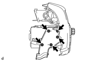 |
8. REMOVE NO. 2 RADIO BRACKET
(a) Remove the 5 screws and No. 2 radio bracket. |
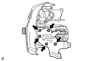 |
1. INSTALL NO. 2 RADIO BRACKET
(a) Install the No. 2 radio bracket with the 5 screws.
Torque:
2,5 N·m {25 kgf·cm, 22 in·lbf}
2. INSTALL NO. 1 RADIO BRACKET
(a) Install the No. 1 radio bracket with the 5 screws.
Torque:
2,5 N·m {25 kgf·cm, 22 in·lbf}
3. INSTALL HAZARD SWITCH WIRE
(a) Connect the connector.
(b) Attach the 2 clamps to install the hazard switch wire.
4. INSTALL NAVIGATION RECEIVER ASSEMBLY WITH BRACKETS
(a) Connect each connector.
(b) Insert the navigation receiver assembly with brackets to attach the 6 claws on its backside. NOTICE: When inserting the navigation receiver assembly with brackets, do not press its knobs on it. |
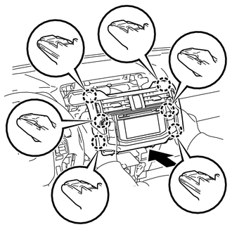 |
(c) Install the navigation receiver assembly with brackets with the 4 bolts.
Torque:
13 N·m {127 kgf·cm, 9 ft·lbf}
5. INSTALL HEATER CONTROL ASSEMBLY

6. INSTALL NO. 2 INSTRUMENT CLUSTER FINISH PANEL GARNISH
7. INSTALL NO. 1 INSTRUMENT CLUSTER FINISH PANEL GARNISH
8. CONNECT CABLE TO NEGATIVE BATTERY TERMINAL
NOTICE:
When disconnecting the cable, some systems need to be initialized after the cable is reconnected (See page ).
9. CHECK SRS WARNING LIGHT
(See page )
Test yourself
A quick Toyota 4Runner quiz: every answer comes with an explanation and a link to the manual page.