Steering
Terminals Of Ecu
In this manual: Steering
~1min read
TERMINALS OF ECU
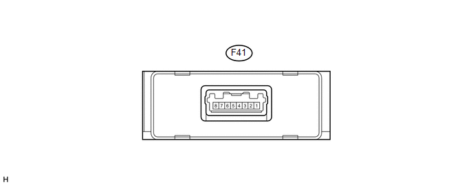
1. CHECK POWER STEERING ECU ASSEMBLY
(a) Measure the voltage and resistance according to the value(s) in the table below.
Terminal No. (Symbol) | Wiring Color | Terminal Description | Condition | Specified Condition |
|---|---|---|---|---|
F41-3 (GND) - Body ground |
W-B - Body ground |
Ground |
Always |
Below 1 Ω |
F41-2 (CANL) - F41-1 (CANH) |
W - L |
CAN communication |
Ignition switch off |
54 to 69 Ω |
F41-5 (IG) - F41-3 (GND) |
G - W-B |
IG power supply |
Ignition switch ON |
11 to 14 V |
F41-7 (SOF+) - F41-8 (SOF-) |
V - LG |
Power steering solenoid valve signal |
|
Pulse generation |
If the result is not as specified, the ECU may have a malfunction.
Test yourself
A quick Toyota 4Runner quiz: every answer comes with an explanation and a link to the manual page.
Was this page helpful?