Transponder Key Amplifier
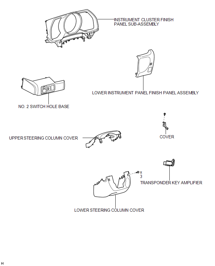
Inspection INSPECTION PROCEDURE
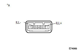
1. INSPECT TRANSPONDER KEY AMPLIFIER
(a) Apply battery voltage to the connector and check the LED illumination condition. OK:
If the result is not as specified, replace the transponder key amplifier. Text in Illustration
|
 |
1. REMOVE NO. 2 SWITCH HOLE BASE

2. REMOVE LOWER INSTRUMENT PANEL FINISH PANEL ASSEMBLY
3. REMOVE INSTRUMENT CLUSTER FINISH PANEL SUB-ASSEMBLY
4. REMOVE LOWER STEERING COLUMN COVER
5. REMOVE UPPER STEERING COLUMN COVER
6. REMOVE TRANSPONDER KEY AMPLIFIER
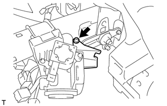
(a) Remove the screw and cover. |
 |
(b) Turn the key amplifier as shown in the illustration to detach the 2 claws and remove the key amplifier. |
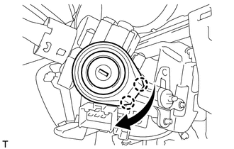 |
(c) Disconnect the connector.
Installation INSTALLATION PROCEDURE1. INSTALL TRANSPONDER KEY AMPLIFIER
(a) Connect the connector. |
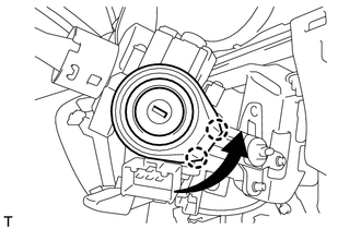 |
(b) Turn the key amplifier as shown in the illustration to attach the 2 claws and install the key amplifier.
(c) Install the cover with the screw.
2. INSTALL UPPER STEERING COLUMN COVER

3. INSTALL LOWER STEERING COLUMN COVER
4. INSTALL INSTRUMENT CLUSTER FINISH PANEL SUB-ASSEMBLY
5. INSTALL LOWER INSTRUMENT PANEL FINISH PANEL ASSEMBLY
6. INSTALL NO. 2 SWITCH HOLE BASE
Test yourself
A quick Toyota 4Runner quiz: every answer comes with an explanation and a link to the manual page.