Unlock Warning Switch
Components
COMPONENTS
ILLUSTRATION
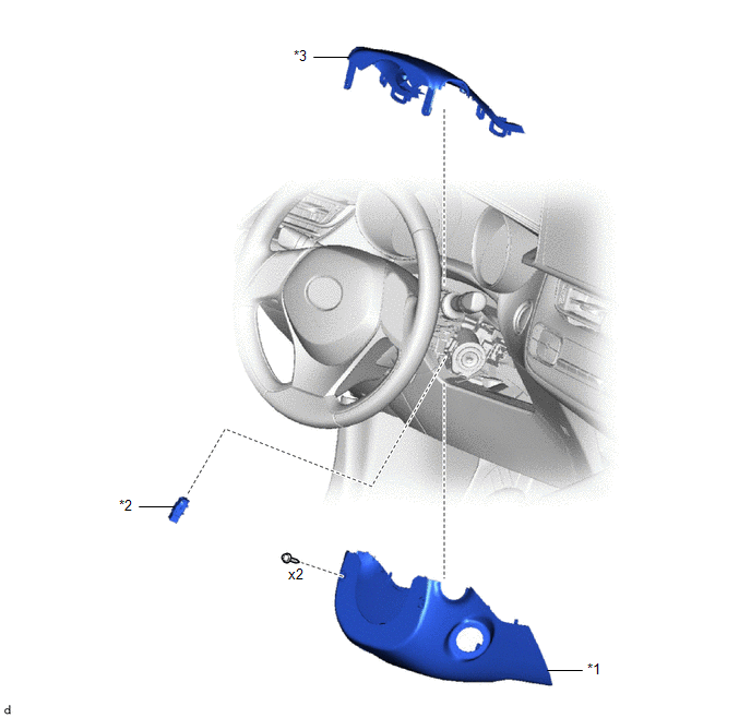
*1 |
LOWER STEERING COLUMN COVER |
*2 |
UNLOCK WARNING SWITCH ASSEMBLY |
*3 |
STEERING COLUMN UPPER COVER |
- |
- |
Removal
REMOVAL
PROCEDURE
1. REMOVE LOWER STEERING COLUMN COVER
Click here
2. REMOVE UPPER STEERING COLUMN COVER
Click here
3. REMOVE UNLOCK WARNING SWITCH ASSEMBLY
(a) Insert the key into the ignition switch. |
|
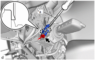
(b) Disconnect the connector.
(c) Using a screwdriver with its tip wrapped in protective tape, release the claws to remove the unlock warning switch assembly.
Inspection
INSPECTION
PROCEDURE
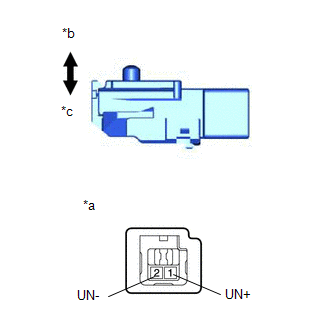
1. INSPECT UNLOCK WARNING SWITCH ASSEMBLY
(a) Check the resistance. (1) Measure the resistance according to the value(s) shown in the table below. Standard resistance:
If the result is not as specified, replace the unlock warning switch assembly. |
|
Installation
INSTALLATION
PROCEDURE
1. INSTALL UNLOCK WARNING SWITCH ASSEMBLY
(a) Engage the claws to install the unlock warning switch assembly. |
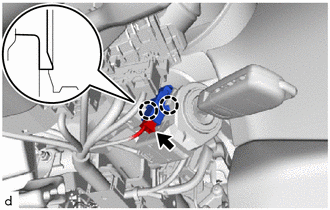 |
(b) Connect the connector.
(c) Remove the key from the ignition switch.
2. REINSTALL UPPER STEERING COLUMN COVER
Click here
3. REINSTALL LOWER STEERING COLUMN COVER
Click here