Door Control Receiver
Components
COMPONENTS
ILLUSTRATION
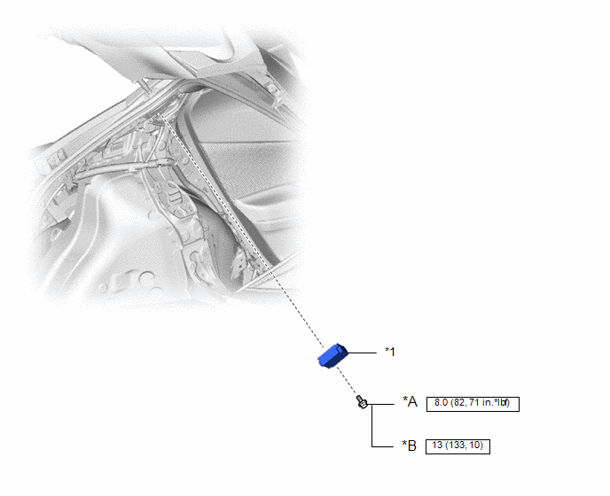
*A |
for type A |
*B |
for type B |
*1 |
DOOR CONTROL RECEIVER AND TIRE PRESSURE MONITORING SYSTEM ASSEMBLY |
- |
- |
 |
N*m (kgf*cm, lbf*in): Specified torque |
- |
- |
Installation
INSTALLATION
PROCEDURE
1. INSTALL DOOR CONTROL RECEIVER AND TIRE PRESSURE MONITORING SYSTEM ASSEMBLY
NOTICE:
- Do not drop, strike or subject the door control receiver and tire pressure monitoring system assembly to impact.
- If the door control receiver and tire pressure monitoring system assembly is subjected to impact, replace it with a new one.
(a) Connect the connector. |
|
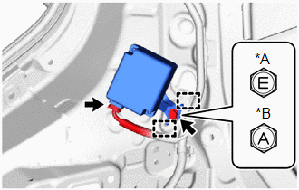
(b) Engage the guides.
(c) Install the door control receiver and tire pressure monitoring system assembly with the bolt.
Torque:
for type A:
8 N·m {82 kgf·cm, 71 in·lbf}
for type B:
13 N·m {133 kgf·cm, 10 ft·lbf}
2. INSTALL LEFT ROOF SIDE INTERIOR GARNISH ASSEMBLY
Click here
Removal
REMOVAL
PROCEDURE
1. REMOVE LEFT ROOF SIDE INTERIOR GARNISH ASSEMBLY
Click here
2. REMOVE DOOR CONTROL RECEIVER AND TIRE PRESSURE MONITORING SYSTEM ASSEMBLY
NOTICE:
- Do not drop, strike or subject the door control receiver and tire pressure monitoring system assembly to impact.
- If the door control receiver and tire pressure monitoring system assembly is subjected to impact, replace it with a new one.
(a) Remove the bolt. |
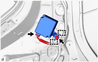 |
(b) Release the guides.
(c) Disconnect the connector to remove the door control receiver and tire pressure monitoring system assembly.