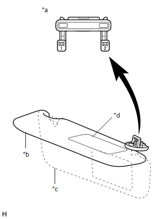
Courtesy Light Switch
Components
COMPONENTS
ILLUSTRATION
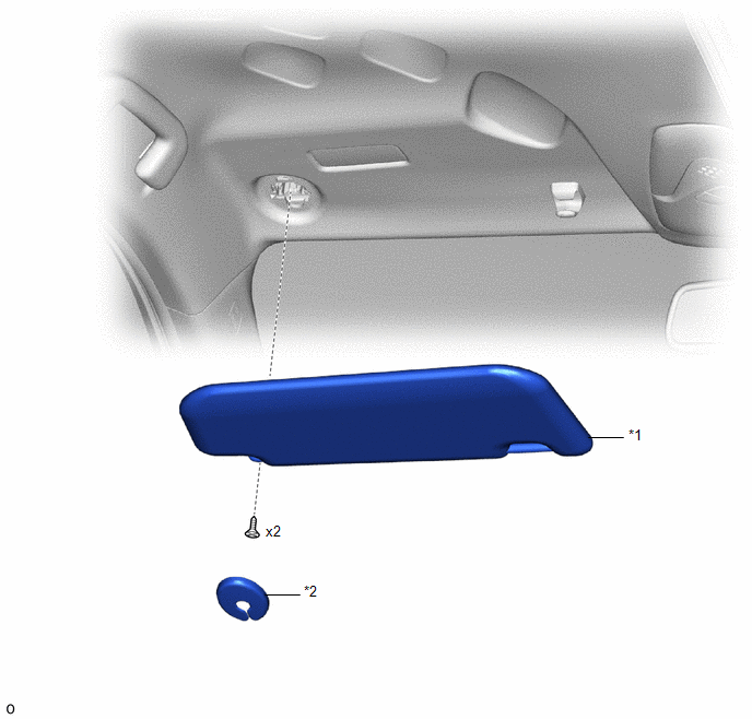
*1 |
SUN VISOR ASSEMBLY |
*2 |
SUN VISOR SUPPORT COVER |
Removal
REMOVAL
PRECAUTION / NOTICE / HINT
HINT:
- Use the same procedure as for the RH and LH sides.
- The procedure described below applies to the left side.
PROCEDURE
1. REMOVE SUN VISOR SUPPORT COVER
Click here
2. REMOVE SUN VISOR ASSEMBLY
(a) Using a TORX T10H bit, remove the 2 screws. |
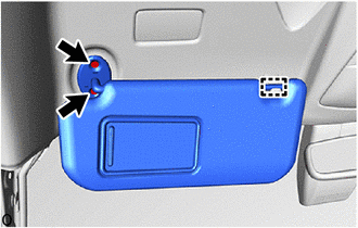 |
(b) Release the guide to remove the sun visor assembly.
Installation
INSTALLATION
PRECAUTION / NOTICE / HINT
HINT:
- Use the same procedure as for the RH and LH sides.
- The procedure described below applies to the left side.
PROCEDURE
1. INSTALL SUN VISOR ASSEMBLY
(a) Engage the guide to install the sun visor assembly. |
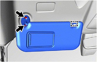 |
(b) Using a TORX T10H bit, install the 2 screws.
2. INSTALL SUN VISOR SUPPORT COVER
Click here
Inspection
INSPECTION
PROCEDURE
1. CHECK LH SUN VISOR ASSEMBLY
(a) Check the resistance. (1) Measure the resistance according to the value(s) shown in the table below. Standard resistance:
If the result is not within specifications, replace the LH sun visor assembly. |
|
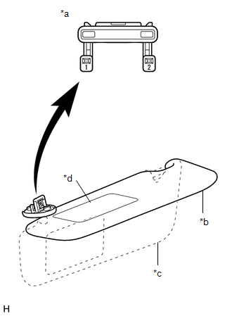
2. CHECK RH SUN VISOR ASSEMBLY
(a) Check the resistance. (1) Measure the resistance according to the value(s) shown in the table below. Standard resistance:
If the result is not within specifications, replace the RH sun visor assembly. |
|