Airbag Deactivation Switch
Components
COMPONENTS
ILLUSTRATION
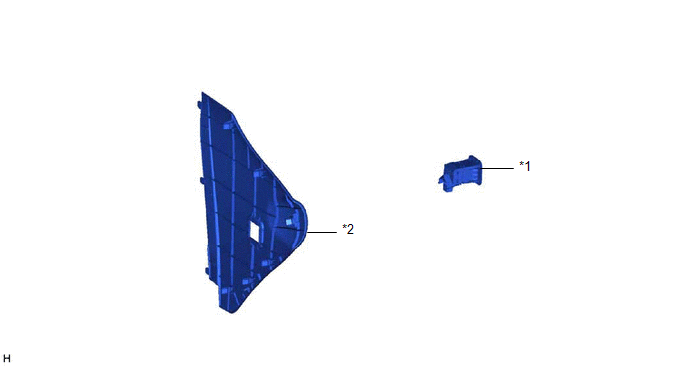
*1 |
AIRBAG DEACTIVATION SWITCH CYLINDER SUB-ASSEMBLY |
*2 |
RH INSTRUMENT PANEL FINISH PANEL END |
Removal
REMOVAL
PROCEDURE
1. REMOVE INSTRUMENT PANEL RH FINISH PANEL END
Click here
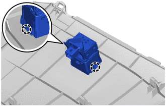
2. REMOVE AIRBAG DEACTIVATION SWITCH CYLINDER SUB-ASSEMBLY
(a) Release the claws to remove the airbag deactivation switch cylinder sub-assembly. |
 |
Inspection
INSPECTION
PROCEDURE
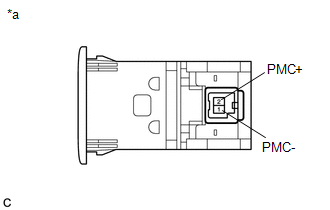
1. INSPECT AIRBAG DEACTIVATION SWITCH CYLINDER SUB-ASSEMBLY
(a) Check the resistance.
(1) Measure the resistance according to the value(s) shown in the table below. Standard resistance:
If the result is not as specified, replace the airbag deactivation switch cylinder sub-assembly. |
|
Installation
INSTALLATION
PROCEDURE
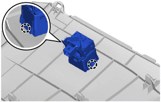
1. INSTALL AIRBAG DEACTIVATION SWITCH CYLINDER SUB-ASSEMBLY
(a) Engage the claws to install the airbag deactivation switch cylinder sub-assembly. |
 |
2. INSTALL INSTRUMENT PANEL RH FINISH PANEL END
Click here