Removal
REMOVAL
PRECAUTION / NOTICE / HINT
The procedures required (adjustment, calibration, initialization or registration) that must be performed after parts have been removed, reinstalled or replaced during removal/installation of the power steering ECU assembly are shown below.
Procedure Required After Replacing / Removing / Installing PartsReplacement part or procedure | Necessary Procedures | Effects / Inoperative Function When Necessary Procedure Not Performed | Link |
|---|---|---|---|
Disconnect the cable from the negative (-) battery terminal. |
Initialize Back Door Lock |
Door Lock Control System |
 |
Memorize Steering Angle Neutral Point |
Lane Departure Alert System (with Steering Control) |
|
|
Pre-Collision System |
|||
Power steering ECU assembly |
|
|
|
PROCEDURE
1. REMOVE THE STEERING COLUMN ASSEMBLY
Click here
2. REMOVE THE POWER STEERING ECU ASSEMBLY
NOTICE:
- Do not drop the power steering ECU assembly, strike it with tools or subject it to impact.
- If the power steering ECU assembly is subjected to impact, replace it with a new one.
- Do not pull on the wire harness when moving the electric power steering column sub-assembly.
- Keep moisture away from the power steering ECU assembly.
- Do not loosen bolts that are not specified in the procedure.
- Do not allow foreign matter to contaminate the power steering ECU assembly.
(a) Disconnect the connector. |
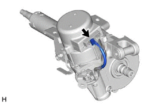 |
(b) for Type A:
(1) Using a "TORX" T40 socket wrench, remove the 2 screws and the power steering ECU assembly from the electric power steering column sub-assembly. |
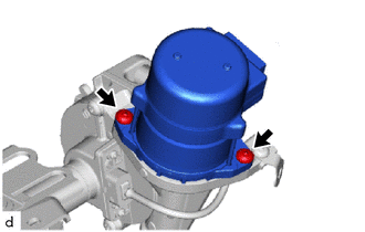 |
(c) for Type B:
(1) Remove the 2 bolts and the power steering ECU assembly from the electric power steering column sub-assembly. |
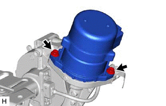 |
3. REMOVE THE POWER STEERING MOTOR SHAFT DAMPER
(a) Remove the power steering motor shaft damper from the electric power steering column sub-assembly. |
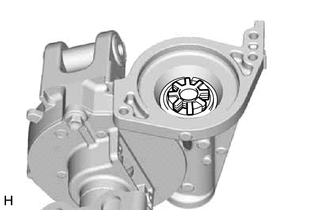 |