Removal
REMOVAL
PROCEDURE
1. REMOVE LH FRONT DOOR SILL PLATE
(a) Release the claws and guides to remove the front LH door sill plate as shown in the illustration.
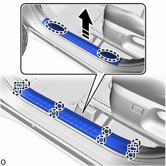
 |
Place hands here |
 |
Remove in this direction |
2. REMOVE LH FENDER APRON SIDE PANEL
(a) Remove the clip.
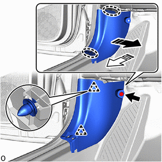
|
Place hands here |
|
Remove in this direction |
(b) Release the clips to remove the LH roof side garnish panel as shown in the illustration.
3. REMOVE NO. 1 INSTRUMENT PANEL LOWER COVER SUB-ASSEMBLY
(a) Remove the 2 screws.
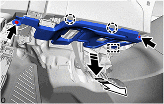
|
Remove in this direction (1) |
 |
Remove in this direction (2) |
(b) Release the claws and guide to remove the No. 1 instrument panel lower cover sub-assembly as shown in the illustration.
4. REMOVE INSTRUMENT CLUSTER FINISH PANEL GARNISH ASSEMBLY
(a) Release the clips to remove the combination meter finish panel garnish sub-assembly as shown in the illustration.
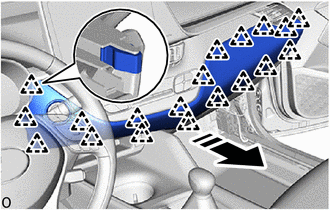
|
Remove in this direction |
5. REMOVE LOWER CENTER INSTRUMENT PANEL FINISH PANEL
(a) Release the clips to remove the instrument panel center lower finish panel as shown in the illustration.
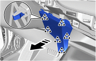
|
Remove in this direction |
(b) Release the claws to disconnect the cooler thermistor. |
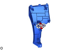 |
6. REMOVE INSTRUMENT PANEL SUB-ASSEMBLY
(a) Release the clips and claw to remove the instrument panel box sub-assembly as shown in the illustration.
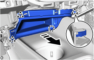
|
Remove in this direction |
(b) with Stereo Jack Adapter:
(1) Disconnect the connector.
7. REMOVE CONSOLE BOX INSERT
(a) Release the clips and guide to remove the console box insert as shown in the illustration.
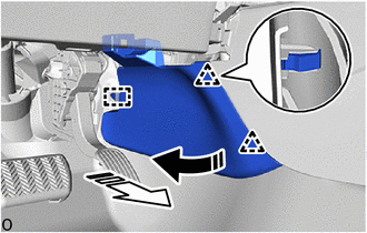
|
Remove in this direction (1) |
|
Remove in this direction (2) |
8. REMOVE FRONT CONSOLE BOX INSERT NO. 2
(a) Release the clips and guide to remove the No. 2 console box insert as shown in the illustration.
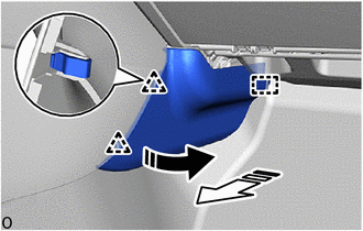
|
Remove in this direction (1) |
|
Remove in this direction (2) |
9. REMOVE SHIFT LEVER KNOB SUB-ASSEMBLY
Click here
10. REMOVE CONSOLE UPPER PANEL SUB-ASSEMBLY
(a) Release the clips to remove the console upper panel sub-assembly as shown in the illustration.
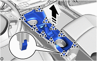
|
Remove in this direction |
(b) Disconnect each connector.
11. REMOVE CONSOLE BOX CUP HOLDER
(a) Release the claws to remove the console box cup holder as shown in the illustration.
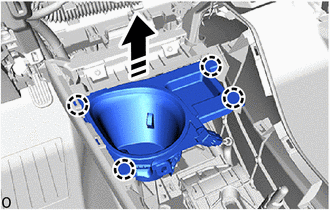
|
Remove in this direction |
(b) with Illumination:
(1) Disconnect the connector.
12. REMOVE CONSOLE BOX CUP HOLDER NO. 2
(a) Release the claws to remove the No. 2 console box cup holder as shown in the illustration.
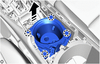
|
Remove in this direction |
(b) with Illumination:
(1) Disconnect the connector.
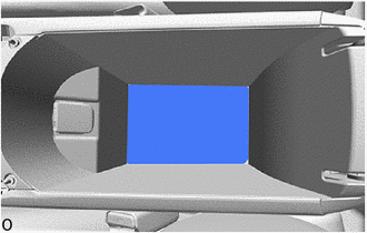
13. REMOVE CONSOLE BOX MAT
(a) Remove the console box mat. |
 |
14. REMOVE REAR CONSOLE BOX ASSEMBLY
(a) Remove the 4 screws. |
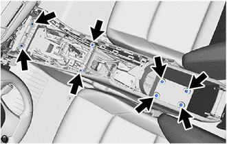 |
(b) Remove the 4 bolts.
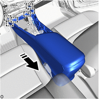
(c) Disconnect the connector.
(d) Release the guides to remove the rear console box assembly as shown in the illustration.
|
Remove in this direction |