Removal
REMOVAL
PRECAUTION / NOTICE / HINT
The procedures required (adjustment, calibration, initialization or registration) that must be performed after parts have been removed and installed or replaced during removal/installation of the rear trailing arm assembly are listed below.
Procedures Required After Replacement / Removal / Installation of PartsReplaced Part or Performed Procedure | Required Procedure | Effect/Inoperative Function When Required Procedure Is Not Performed | Link |
|---|---|---|---|
Rear Wheel Alignment Adjustment |
|
|
 |
HINT:
- Repeat the same procedure for the right side and the left side.
- The following procedure applies to the left side.
PROCEDURE
1. REMOVE REAR WHEEL
Click here
2. DISCONNECT NO. 2 REAR PARKING BRAKE CABLE ASSEMBLY
(a) Using a screwdriver with its tip wrapped in protective tape, disconnect the No. 2 rear parking brake cable connector from the rear axle hub and bearing assembly. NOTICE: Be careful not to damage the rear axle hub and bearing assembly or the connector cover. |
|
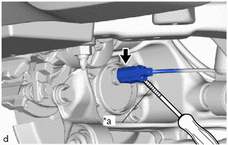
(b) Release the clip. |
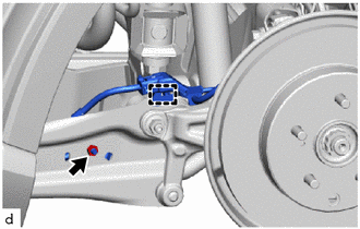 |
(c) Remove the nut to disconnect the No. 2 rear parking brake cable assembly from the rear trailing arm assembly.
3. REMOVE REAR STABILIZER LINK ASSEMBLY
Click here
4. REMOVE REAR TRAILING ARM ASSEMBLY
(a) Using a transmission jack and a wooden block, support the No. 2 rear suspension arm assembly. NOTICE:
|
|
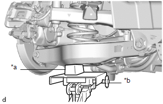
(b) Remove the 2 bolts to disconnect the rear trailing arm assembly from the rear axle carrier sub-assembly. |
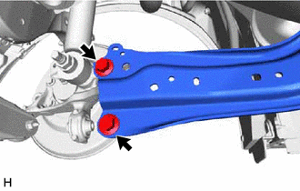 |
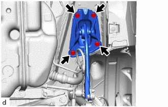
(c) Remove the 4 bolts and the rear trailing arm assembly. |
 |
5. REMOVE REAR SUSPENSION SUPPORT COVER NO. 1
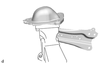
(a) Secure the rear trailing arm assembly in a vise between aluminum plates. NOTICE: Do not overtighten the vise. |
 |
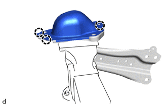
(b) Release the 3 claws to remove the rear suspension support cover No. 1. |
 |
6. REMOVE REAR SUSPENSION ARM BRACKET
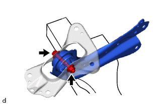
(a) Remove the bolt, nut and rear suspension arm bracket from the rear trailing arm assembly. NOTICE: Do not turn the bolt as it has a stopper. Loosen the nut with the bolt in place. |
 |