Installation
INSTALLATION
PROCEDURE
1. INSTALL HOLE PLUG
(a) Install the 4 hole plugs to the front suspension crossmember sub-assembly.
HINT:
There are 2 different types of hole plugs.
2. INSTALL FRONT SUSPENSION CROSSMEMBER PLATE
(a) Install the 2 front suspension crossmember plates to the front suspension crossmember sub-assembly.
3. INSTALL ENGINE POSITION CONTROL ROD
(a) Install the engine position control rod to the front suspension crossmember sub-assembly with the bolt.
Torque:
200 N·m {2 039 kgf·cm, 148 ft·lbf}
4. TEMPORARILY INSTALL NO. 1 FRONT LOWER SUSPENSION ARM SUB-ASSEMBLY LH
(a) Temporarily install the front suspension lower arm sub-assembly No. 1 LH onto the front suspension crossmember sub-assembly with the 2 bolts and nut.
5. TEMPORARILY INSTALL NO. 1 FRONT LOWER SUSPENSION ARM SUB-ASSEMBLY RH
HINT:
Perform the same procedure as for the left side.
6. INSTALL FRONT STABILIZER BAR
Click here
7. INSTALL NO. 1 FRONT STABILIZER BAR BRACKET LH
Click here
8. INSTALL NO. 1 FRONT STABILIZER BAR BRACKET RH
HINT:
Perform the same procedure as for the left side.
9. INSTALL STEERING TIE ROD ASSEMBLY
(a) Install the steering tie rod assembly onto the front suspension crossmember sub-assembly with the 2 new bolts and 2 new nuts.
Torque:
133 N·m {1,356 kgf·cm, 98 ft·lbf}
NOTICE:
- Do not turn the nut as it has a stopper. Tighten the bolt with the nut in place.
- Be sure to tighten the bolts starting from the left side of the vehicle.
10. INSTALL FRONT SUSPENSION CROSSMEMBER SUB-ASSEMBLY
(a) Slowly raise the front suspension crossmember sub-assembly using an engine jack with the 4 attachments or equivalent tools.
CAUTION:
- The front suspension crossmember sub-assembly is a very heavy component. Make sure it is properly supported.
- If the front suspension crossmember sub-assembly is not properly supported, it may fall and cause serious injury.
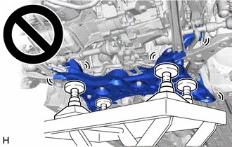
NOTICE:
Use the attachments to keep the front suspension crossmember sub-assembly level.
(b) Install the front suspension crossmember sub-assembly to the body with the 6 bolts.
Torque:
141 N·m {1 438 kgf·cm, 104 ft·lbf}
(c) Lower the engine jack.
(d) Install the engine position control rod with the bolt.
Torque:
170 N·m {1 734 kgf·cm, 125 ft·lbf}
(e) Install the 2 wire harness clamp brackets to the front suspension crossmember sub-assembly with the 2 bolts.
Torque:
13 N·m {133 kgf·cm, 10 ft·lbf}
11. INSTALL NO. 1 FRONT LOWER SUSPENSION ARM SUB-ASSEMBLY LH
(a) Install the No. 1 front lower suspension arm sub-assembly to the LH front lower ball joint assembly with the bolt and 2 nuts.
Torque:
89 N·m {908 kgf·cm, 66 ft·lbf}
12. CONNECT NO. 1 FRONT LOWER SUSPENSION ARM SUB-ASSEMBLY RH
HINT:
Perform the same procedure as for the left side.
13. CONNECT STEERING TIE ROD END SUB-ASSEMBLY LH
Click here
14. CONNECT STEERING TIE ROD END SUB-ASSEMBLY RH
HINT:
Perform the same procedure as for the left side.
15. CONNECT FRONT STABILIZER LINK ASSEMBLY LH
(a) Connect the LH front stabilizer link assembly to the front shock absorber assembly with the nut.
Torque:
74 N·m {755 kgf·cm, 55 ft·lbf}
NOTICE:
Be careful not to damage the ball joint boot.
HINT:
If the ball joint turns together with the nut, hold the stud with a 6 mm hexagon socket wrench.
16. CONNECT FRONT STABILIZER LINK ASSEMBLY RH
HINT:
Perform the same procedure as for the left side.
17. INSTALL LH SIDE MEMBER REAR BRACE SUB-ASSEMBLY
(a) Install the LH side member rear brace sub-assembly to the front suspension crossmember sub-assembly and body with the 4 bolts.
Torque:
70 N·m {714 kgf·cm, 52 ft·lbf}
18. INSTALL RH SIDE MEMBER REAR BRACE SUB-ASSEMBLY
HINT:
Perform the same procedure as for the left side.
19. CONNECT NO. 1 STEERING COLUMN HOLE COVER SUB-ASSEMBLY
Click here
20. CONNECT STEERING INTERMEDIATE SHAFT ASSEMBLY NO. 2
Click here
21. INSTALL STEERING COLUMN HOLE COVER INSULATOR
Click here
22. INSTALL FRONT WHEELS
Click here
23. STABILIZE SUSPENSION
Click here
24. FULLY TIGHTEN NO. 1 FRONT LOWER SUSPENSION ARM SUB-ASSEMBLY LH
Click here
25. FULLY TIGHTEN NO. 1 FRONT LOWER SUSPENSION ARM SUB-ASSEMBLY RH
HINT:
Perform the same procedure as for the left side.
26. INSTALL FRONT FLOOR PANEL COVER LH (with cover)
Click here
27. INSTALL FRONT FLOOR PANEL COVER RH (with cover)
HINT:
Perform the same procedure as for the left side.
28. INSTALL LH REAR ENGINE UNDER COVER
Click here
29. INSTALL RH REAR ENGINE UNDER COVER
Click here
30. INSTALL NO. 1 ENGINE UNDER COVER
Click here
31. INSPECT AND ADJUST FRONT WHEEL ALIGNMENT
Click here
32. PERFORM INITIALIZATION (with height control sensor)
Click here