Heated Steering Wheel System
Precautions
PRECAUTION
PRECAUTIONS WHEN HANDLING THE SRS AIRBAG SYSTEM
(a) The vehicle is equipped with a supplemental restraint system (SRS). Failure to follow the correct service operation sequence may cause the SRS to deploy accidentally during servicing, which may result in a serious accident.
Before performing any service operation (inspection, replacement, removal and installation of parts), be sure to read carefully the precautions for the supplemental restraint system.
Click here
Component Locations
COMPONENT LOCATIONS
ILLUSTRATION
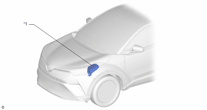
*1 |
ENGINE ROOM RELAY BLOCK NO. 1 - STRG HTR FUSE |
- |
- |
ILLUSTRATION
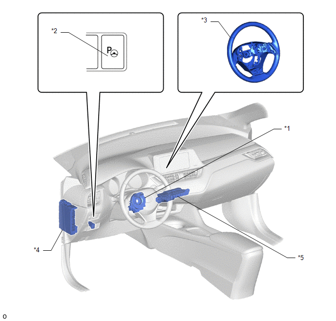
*1 |
SPIRAL CABLE SUB-ASSEMBLY WITH SENSOR |
*2 |
STEERING WHEEL HEATER SWITCH |
*3 |
STEERING WHEEL ASSEMBLY - STEERING HEATER UNIT |
*4 |
INSTRUMENT PANEL JUNCTION BLOCK ASSEMBLY - ECU-IG1 FUSE NO. 4 |
*5 |
RELAY BLOCK ASSEMBLY NO. 4 - STRG HTR RELAY |
- |
- |
System Diagram
SYSTEM DIAGRAM
System Description
SYSTEM DESCRIPTION
HEATED STEERING WHEEL SYSTEM
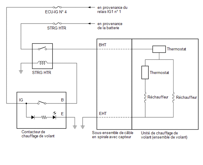
(a) The steering heater heats the steering wheel when the steering heater switch is turned ON.
(b) The steering heater uses a control thermostat located inside the steering wheel to maintain the steering wheel at the specified temperature.
OPERATION DESCRIPTION
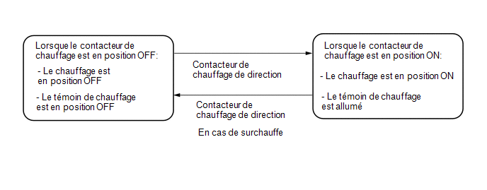
(a) When the steering heater switch is turned ON with the ignition switch ON, the heater indicator light on the combination meter comes on and the heater inside the steering wheel is activated. If the steering heater switch is pressed again, the heater indicator light on the combination meter goes off and the heater stops operating.
(b) A control thermostat and an additional thermostat used as a safety device to prevent overheating are installed in the steering wheel.
CONTROL DESCRIPTION
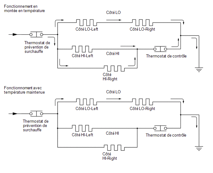
(a) When the steering heater switch is turned on, current flows to the HI and LO sides and heating begins to warm the steering wheel.
(b) When the steering wheel temperature reaches the control thermostat operating temperature, the control thermostat cuts current flow to the HI side and allows current to flow only to the LO side, thereby maintaining the steering wheel temperature.
(c) While maintaining the steering wheel temperature, if the temperature drops to the control thermostat operating temperature, the control thermostat restarts current flow to the LO and HI sides to heat the steering wheel.
(d) While the steering heater switch is on, the control thermostat automatically cuts off and restarts current flow to the HI side based on the steering wheel temperature, thereby constantly maintaining the specified temperature.
(e) If a malfunction occurs in the steering heater circuit and the temperature exceeds the specified temperature, the overheat prevention thermostat cuts current flow to the circuit, the heater indicator light on the combination meter assembly goes off and the heater stops operating.
Symptom Table
SYMPTOM TROUBLESHOOTING TABLE
HINT:
Use the table below to determine the cause of the symptoms. If several suspected areas are listed, the possible causes of the symptom are shown in order of probability in the "Suspected Area" column of the table. Check each symptom, verifying the suspected areas in the order listed. Replace parts if necessary.
Heated Steering Wheel SystemSymptom | Suspected Area | Link |
|---|---|---|
Steering wheel does not heat when steering heater switch is pressed |
STRG HTR fuse |
- |
ECU-IG1 NO. 4 fuse |
- |
|
STRG HTR relay |
- |
|
Steering heater switch |
 |
|
Spiral cable sub-assembly with sensor |
|
|
Steering wheel heater unit (steering wheel assembly) |
|