Installation
INSTALLATION
COMPONENTS (INSTALLATION)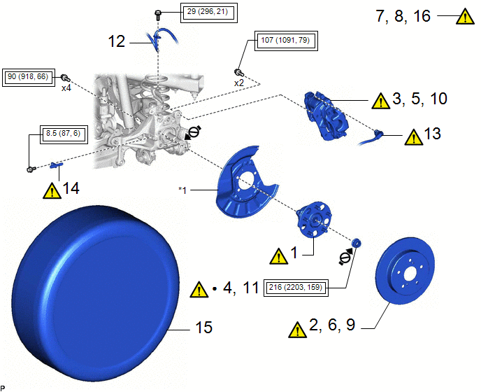
Procedure | Part Name Code |  |  |  |
|
|---|---|---|---|---|---|
1 |
REAR AXLE HUB AND BEARING ASSEMBLY |
42450B |
 |
- |
- |
2 |
INSTALL REAR DISC |
42431 |
|
- |
- |
3 |
INSTALL REAR DISC BRAKE CALIPER ASSEMBLY |
- |
|
- |
- |
4 |
TEMPORARILY INSTALL REAR AXLE SHAFT NUT |
42312B |
|
- |
- |
5 |
SEPARATE REAR DISC BRAKE CALIPER ASSEMBLY |
- |
|
- |
- |
6 |
REMOVE REAR DISC |
42431 |
|
- |
- |
7 |
INSPECT REAR AXLE HUB BEARING LOOSENESS |
- |
|
- |
- |
8 |
INSPECT REAR AXLE HUB RUNOUT |
- |
|
- |
- |
9 |
INSTALL REAR DISC |
42431 |
|
- |
- |
10 |
INSTALL REAR DISC BRAKE CALIPER ASSEMBLY |
- |
|
- |
- |
11 |
STAKE REAR AXLE SHAFT NUT |
42312B |
|
- |
- |
12 |
REAR FLEXIBLE HOSE |
47319F |
- |
- |
- |
13 |
NO. 2 PARKING BRAKE WIRE ASSEMBLY |
890C0A |
|
- |
- |
14 |
REAR SKID CONTROL SENSOR |
89544E |
|
- |
- |
15 |
REAR WHEEL |
- |
- |
- |
- |
16 |
CHECK FOR SPEED SENSOR SIGNAL |
- |
|
- |
- |
*1 |
REAR DISC BRAKE DUST COVER SUB-ASSEMBLY |
- |
- |
 |
Tightening torque for "Major areas involving basic vehicle performance such as moving/turning/stopping": N*m (kgf*cm, ft.*lbf) |
● |
Non-reusable part |
 |
Do not apply lubricants to the threaded parts |
- |
- |
HINT:
- Use the same procedure for the RH side and LH side.
- The following procedure is for the LH side.
PROCEDURE
1. INSTALL REAR AXLE HUB AND BEARING ASSEMBLY
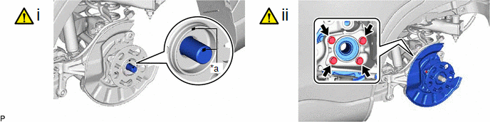
*a |
Matchmark |
- |
- |
(1) Install the rear axle hub and bearing assembly and rear disc brake dust cover sub-assembly to the rear drive shaft assembly.
NOTICE:
Align the matchmarks on the rear drive shaft assembly and rear axle hub and bearing assembly.
(2) Install the rear axle hub and bearing assembly to the rear axle carrier sub-assembly with the 4 bolts.
Torque:
90 N·m {918 kgf·cm, 66 ft·lbf}
NOTICE:
Do not damage the rear drive shaft outboard joint boot.
2. INSTALL REAR DISC
|
Click here |
3. INSTALL REAR DISC BRAKE CALIPER ASSEMBLY
|
Click here |
4. TEMPORARILY INSTALL REAR AXLE SHAFT NUT
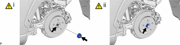
(1) Clean the threaded parts on the rear drive shaft assembly and a new rear axle shaft nut using non-residue solvent.
NOTICE:
- Be sure to perform this work even when using a new rear drive shaft assembly.
- Keep the threaded parts free of oil and foreign matter.
(2) Using a 30 mm deep socket wrench, temporarily install the rear axle shaft nut.
Torque:
216 N·m {2203 kgf·cm, 159 ft·lbf}
NOTICE:
- Stake the rear axle shaft nut after inspecting for looseness and runout in the following steps.
- Keep depressing the brake pedal to prevent the rear drive shaft assembly from rotating.
5. SEPARATE REAR DISC BRAKE CALIPER ASSEMBLY
|
Click here |
6. REMOVE REAR DISC
|
Click here |
7. INSPECT REAR AXLE HUB BEARING LOOSENESS
Click here
8. INSPECT REAR AXLE HUB RUNOUT
Click here
9. INSTALL REAR DISC
|
Click here |
10. INSTALL REAR DISC BRAKE CALIPER ASSEMBLY
|
Click here |
11. STAKE REAR AXLE SHAFT NUT
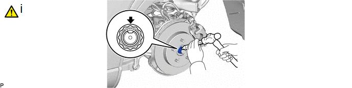
(1) Using a chisel and hammer, stake the rear axle shaft nut.
12. INSTALL REAR FLEXIBLE HOSE
Click here
13. CONNECT NO. 2 PARKING BRAKE WIRE ASSEMBLY
|
Click here |
14. INSTALL REAR SKID CONTROL SENSOR
|
Click here |
15. INSTALL REAR WHEEL
Click here
16. CHECK FOR SPEED SENSOR SIGNAL
- for HEV Model:
Click here
- for Gasoline Model:
Click here