Audio & Visual & Telematics
On-vehicle Inspection
ON-VEHICLE INSPECTION
PROCEDURE
1. INSPECT RADIO SETTING CONDENSER
(a) With the radio setting condenser installed, check that there is no looseness or other abnormalities.
(b) Measure the resistance of the radio setting condenser according to the value(s) in the table below.
Standard Resistance:
Tester Connection | Condition | Specified Condition |
1 - Body ground |
- Ignition switch off
- Window Defogger turned off
- High mounted stop light off
|
Below 1 Ω |
|
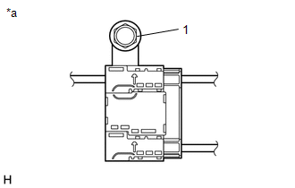 |
*a |
Radio Setting Condenser |
|
|
(c) Remove the bolt.
(d) Disengage the clamp and disconnect the radio setting condenser with wire harness from the vehicle body.
(e) Measure the resistance and voltage of the radio setting condenser according to the value(s) in the table below.
Standard Resistance:
Tester Connection | Condition | Specified Condition |
1 - 2 |
- Ignition switch off
- Window Defogger turned off
- High mounted stop light off
|
10 kΩ or higher |
1 - 3 |
10 kΩ or higher |
Standard Voltage:
Tester Connection | Condition | Specified Condition |
2 - Body ground |
- Ignition switch ON
- Window Defogger turned off
|
Below 1 V |
3 - Body ground |
- Ignition switch ON
- High mounted stop light off
|
Below 1 V |
2 - Body ground |
- Ignition switch ON
- Window Defogger turned on
|
11 to 14 V |
3 - Body ground |
- Ignition switch ON
- High mounted stop light on
|
11 to 14 V |
|
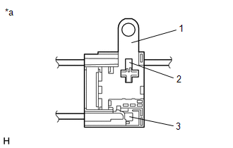 |
*a |
Radio Setting Condenser |
|
|
Was this page helpful?