Room Temperature Sensor
Removal
REMOVAL
COMPONENTS (REMOVAL)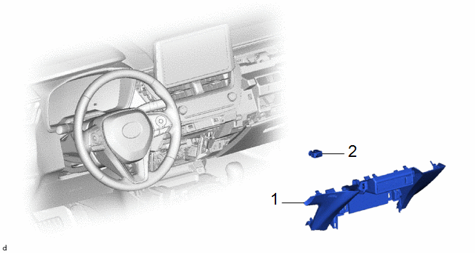
Procedure | Part Name Code |  |  |  |
|
|---|---|---|---|---|---|
1 |
LOWER CENTER INSTRUMENT PANEL FINISH PANEL |
55434F |
- |
- |
- |
2 |
COOLER THERMISTOR (ROOM TEMPERATURE SENSOR) |
88625Q |
- |
- |
- |
PROCEDURE
1. REMOVE LOWER CENTER INSTRUMENT PANEL FINISH PANEL
Click here 
2. REMOVE COOLER THERMISTOR (ROOM TEMPERATURE SENSOR)
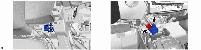
Inspection
INSPECTION
PROCEDURE
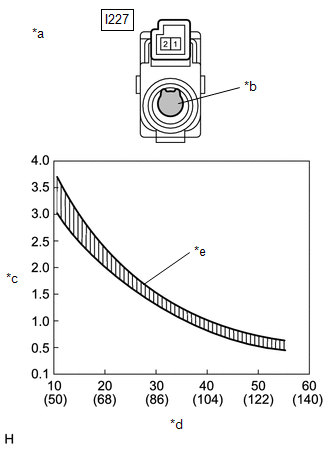
1. INSPECT COOLER THERMISTOR (ROOM TEMPERATURE SENSOR)
(a) Check the resistance.
(1) Measure the resistance according to the value(s) in the table below. Standard Resistance:
NOTICE:
HINT: As the temperature increases, the resistance decreases (see the graph). If the result is not as specified, replace the cooler thermistor (room temperature sensor). |
|
Installation
INSTALLATION
COMPONENTS (INSTALLATION)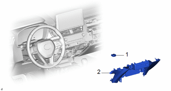
Procedure | Part Name Code |  |  |  |
|
|---|---|---|---|---|---|
1 |
COOLER THERMISTOR (ROOM TEMPERATURE SENSOR) |
88625Q |
- |
- |
- |
2 |
LOWER CENTER INSTRUMENT PANEL FINISH PANEL |
55434F |
- |
- |
- |
PROCEDURE
1. INSTALL COOLER THERMISTOR (ROOM TEMPERATURE SENSOR)
2. INSTALL LOWER CENTER INSTRUMENT PANEL FINISH PANEL
Click here 