Disassembly
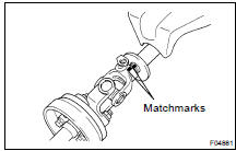
NOTICE: When using a vise, do not overtighten it.
1. REMOVE NO. 2 LOWER COVER
Remove the 2 nuts and lower side No. 2 lower cover.
2. REMOVE INTERMEDIATE SHAFT ASSEMBLY
(a) Place matchmarks on the intermediate shaft assembly and main shaft assembly. (b) Remove the bolt and intermediate shaft assembly with the upper side No. 2 lower cover.(c) Remove the thrust stopper from the main shaft assembly.
3. REMOVE TRANSPONDER KEY AMPLIFIER
(a) Widen the claw humg on the upper bracket by approx. 1.0 mm (0.039 in.) using a screwdriver.(b) Pull the transponder key amplirier toward the rear of the vehicle with the claw open.
NOTICE: Take care not to use excessive force to prevent the case from being damage.
4. REMOVE COLUMN UPPER BRACKET AND COLUMN UPPER CLAMP
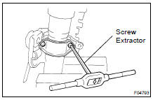
(c) Using a screw extractor, remove the 2 bolts, column upper bracket and column upper clamp.
5. REMOVE COLUMN TUBE SUPPORT
(a) Remove the bolt. (b) Remove the column tube support with tube attachment.(c) Remove the tube attachment from the column tube support.
6. REMOVE 2 ENERGY ABSORBING PLATES
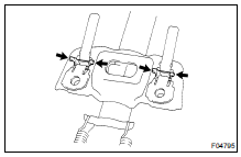
(b) Remove the 2 energy absorbing plates and 2 energy absorbing guides.
7. REMOVE 4 TENSION SPRINGS
HINT: Remove the springs with the tilt function at maximum tilt up.
8. REMOVE TILT LEVER

(c) Remove the 2 bushings from the column upper tube.
9. REMOVE TILT LEVER LINK
10. REMOVE COLUMN UPPER TUBE WITH MAIN SHAFT ASSEMBLY
(a) Using a hexagon wrench, remove the 2 tilt steering bolts.(b) Remove the upper tube with the main shaft assembly from the column tube.
11. REMOVE TILT LEVER RETAINER
12. REMOVE MAIN SHAFT ASSEMBLY

(a) Using SST, compress the compression spring.
SST 09950-4001 1 (09958-04011)
NOTICE: Do not bend the universal joint of the shaft more than 20.
(b) Using a snap ring expander, remove the snap ring from the shaft. (c) Remove the shaft assembly from the column upper tube.(d) Remove the compression spring and bearing thrust collar from the shaft.
13. REMOVE TURN SIGNAL BRACKET
Remove the 2 bolts and turn signal bracket.
14. REMOVE TILT STEERING PAWL
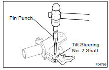
(c) Remove the pin from the pawl.
15. REMOVE BUSHING
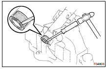
Using a screwdriver, tap out the bushing.
Test yourself
A quick Toyota Land Cruiser quiz: every answer comes with an explanation and a link to the manual page.