Theft deterrent
ECU Power Source Circuit
In this manual: Theft deterrent
6steps
~36min
2/5difficulty
Done 0 of 6
DESCRIPTION
This circuit provides power to operate the theft deterrent (warning) ECU.
WIRING DIAGRAM
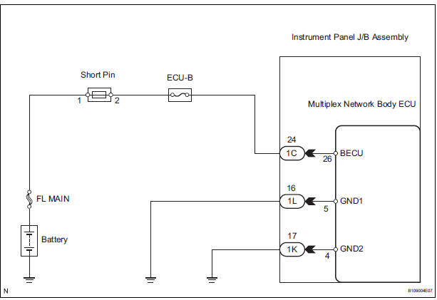
INSPECTION PROCEDURE
1 INSPECT FUSE (ECU-B)
- Remove the ECU-B fuse from the engine room J/B.
- Measure the resistance.
2 CHECK INSTRUMENT PANEL J/B ASSEMBLY (POWER SOURCE)
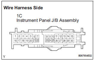
- Disconnect the 1C J/B connector.
- Measure the voltage according to the value(s) in the table below.
Standard voltage

3 CHECK HARNESS AND CONNECTOR (INSTRUMENT PANEL J/B ASSEMBLY - BODY GROUND)
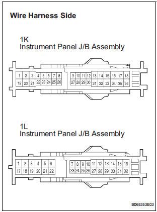
- Disconnect the 1K and 1L J/B connector.
- Measure the resistance according to the value(s) in the table below.
Standard resistance

REPLACE INSTRUMENT PANEL J/B ASSEMBLY
Test yourself
A quick Toyota Sienna quiz: every answer comes with an explanation and a link to the manual page.
Was this page helpful?