Theft deterrent
Ignition Switch Circuit
In this manual: Theft deterrent
9steps
~54min
2/5difficulty
Done 0 of 9
DESCRIPTION
When the ignition switch is turned to the ON position, battery positive voltage is applied to terminal IG of the ECU. When battery positive voltage is applied to terminal IG of the ECU while the theft deterrent system is operating, the warning stops.
WIRING DIAGRAM
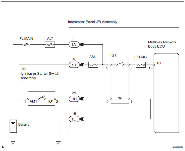
INSPECTION PROCEDURE
1 INSPECT FUSES (ECU-IG, AM1)
- Remove the ECU-IG and AM1 fuses from the instrument panel J/B.
- Measure the resistance.
2 INSPECT RELAY (IG1)
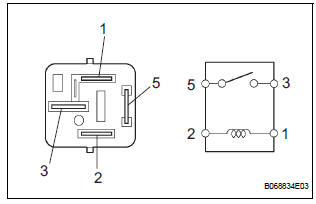
- Remove the IG1 relay from the instrument panel J/B.
- Check the operation of the IG1 relay.
Standard resistance
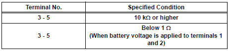
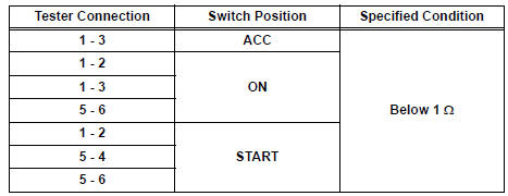
3 INSPECT IGNITION OR STARTER SWITCH ASSEMBLY
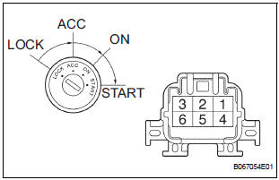
- Disconnect the I15 switch connector.
- Measure the resistance according to the value(s) in the table below.
Standard resistance
4 CHECK INSTRUMENT PANEL JUNCTION BLOCK ASSEMBLY (POWER SOURCE)

- Disconnect the 1A J/B connector.
- Turn the ignition switch ON.
- Measure the voltage according to the value(s) in the table below.
Standard voltage

REPLACE INSTRUMENT PANEL J/B ASSEMBLY
Test yourself
A quick Toyota Sienna quiz: every answer comes with an explanation and a link to the manual page.
Was this page helpful?