Can communication
Terminals of ECU
In this manual: Can communication
12steps
~72min
3/5difficulty
Done 0 of 12
1. JUNCTION CONNECTOR
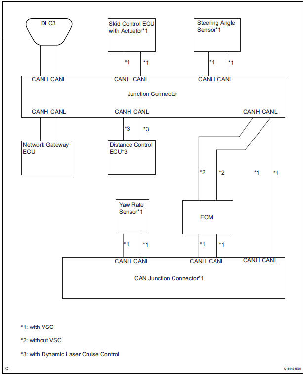
- Junction connector
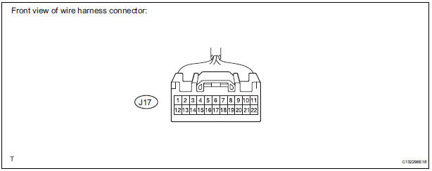
with VSC
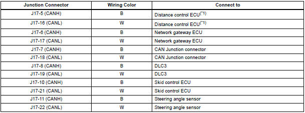
HINT: *1: with Dynamic laser cruise control
without VSC
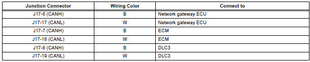
- CAN junction connector (with VSC)
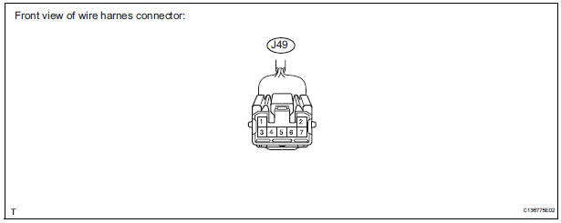
with VSC

- The connection diagram of the components which are connected to the CAN junction connector.
2. DLC3
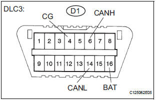
- Measure the resistance according to the value(s) in the table below.
Standard resistance

3. ECM
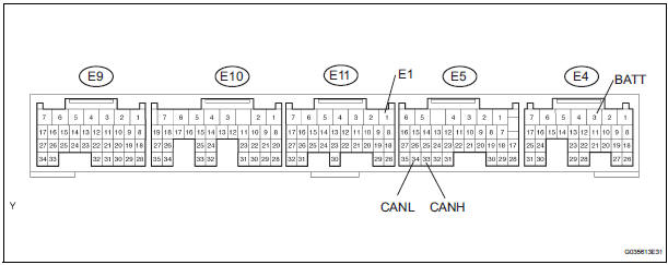
- Disconnect the connector from the ECM.
- Measure the resistance according to the value(s) in the table below
Standard resistance

4. NETWORK GATEWAY ECU
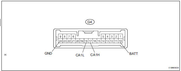
- Disconnect the connector from the netwark gateway ECU.
- Measure the resistance according to the value(s) in the table below
Standard resistance

5. SKID CONTROL ECU WITH ACTUATOR

- Disconnect the connector from the skid control ECU with actuator.
- Measure the resistance according to the value(s) in the table below
Standard resistance


6. STEERING ANGLE SENSOR

- Disconnect the connector from the steering angle sensor.
- Measure the resistance according to the value(s) in the table below.
Standard resistance

7. YAW RATE SENSOR
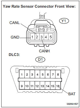
- Disconnect the connector from the yaw rate sensor.
- Measure the resistance according to the value(s) in the table below.
Standard resistance

8. DISTANCE CONTROL ECU

- Disconnect the connector from the distance control ECU.

- Measure the resistance according to the value(s) in the table below.
Standard resistance

Test yourself
A quick Toyota Sienna quiz: every answer comes with an explanation and a link to the manual page.
Was this page helpful?