Clearance Sonar Main Switch
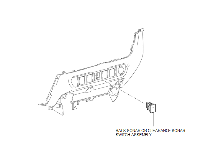 Removal REMOVAL PROCEDURE
1. REMOVE INSTRUMENT PANEL LOWER CENTER FINISH PANEL
(See page  )
2. REMOVE BACK SONAR OR CLEARANCE SONAR SWITCH ASSEMBLY
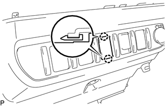
(a) Disengage the 2 claws to remove the back sonar or clearance sonar switch assembly. |
 |
1. INSPECT BACK SONAR OR CLEARANCE SONAR SWITCH ASSEMBLY
(a) Check the resistance.
(1) Measure the resistance according to the value(s) in the table below. Text in Illustration
Standard Resistance:
If the result is not as specified, replace the back sonar or clearance sonar switch assembly. |
 |
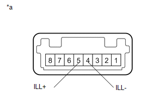
(b) Check the illumination operation.
(1) Apply battery voltage to the back sonar or clearance sonar switch assembly and check that the switch illuminates. Text in Illustration
If the result is not as specified, replace the back sonar or clearance sonar switch assembly. |
 |
1. INSTALL BACK SONAR OR CLEARANCE SONAR SWITCH ASSEMBLY
(a) Engage the 2 claws to install the back sonar or clearance sonar switch assembly.
2. INSTALL INSTRUMENT PANEL LOWER CENTER FINISH PANEL
(See page  )
Test yourself
A quick Toyota Tacoma quiz: every answer comes with an explanation and a link to the manual page.