Fuel Sender Gauge Assembly
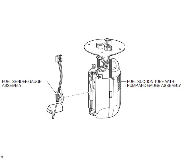 Inspection INSPECTION PROCEDURE
1. INSPECT FUEL SENDER GAUGE ASSEMBLY
(a) Check that the float moves smoothly between F and E. Text in Illustration
|
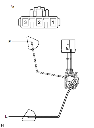 |
(b) Measure the resistance according to the value(s) in the table below.
Standard Resistance:
Tester Connection | Condition | Specified Condition |
|---|---|---|
2 - 3 |
Float position is F (upper) |
13.5 to 16.5 Ω |
Float position is E (lower) |
405.5 to 414.5 Ω |
If the result is not as specified, replace the fuel sender gauge assembly.
Removal REMOVAL PROCEDURE1. REMOVE FUEL SUCTION TUBE WITH PUMP AND GAUGE ASSEMBLY
(See page  )
2. REMOVE FUEL SENDER GAUGE ASSEMBLY
(a) Disconnect the fuel sender gauge assembly connector. |
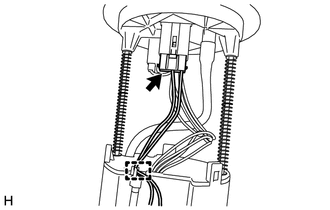 |
(b) Disengage the clamp and disconnect the wire harness.
(c) Press down on the fuel sender gauge claw labeled A. Then slide the fuel sender gauge assembly upward to remove it.
 Text in Illustration
 |
Press down |
 |
Slide |
1. INSTALL FUEL SENDER GAUGE ASSEMBLY
(a) Set the fuel sender gauge assembly on the No. 1 fuel sub-tank. Then slide the fuel sender gauge assembly downward to install it.
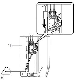 Text in Illustration
*1 |
No. 1 Fuel Sub-Tank |
 |
Slide |
(b) Engage the clamp and connect the wire harness.
(c) Connect the fuel sender gauge assembly connector.
2. INSTALL FUEL SUCTION TUBE WITH PUMP AND GAUGE ASSEMBLY
(See page  )
Test yourself
A quick Toyota Tacoma quiz: every answer comes with an explanation and a link to the manual page.