Vehicle Interior
Rear Door Courtesy Switch
In this manual: Vehicle Interior
~1min read
ComponentsCOMPONENTSILLUSTRATION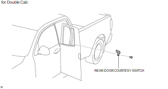
ILLUSTRATION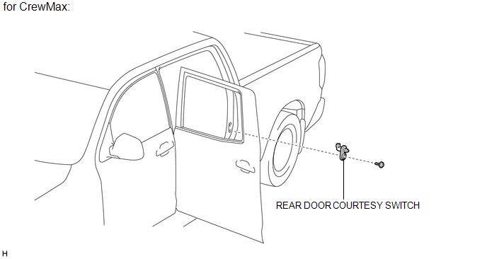
InspectionINSPECTIONPROCEDURE1. INSPECT REAR DOOR COURTESY SWITCH 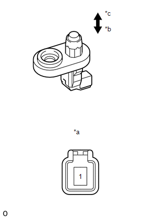
(a) Measure the resistance according to the value(s) in the table below. Standard Resistance:
If the result is not as specified, replace the rear door courtesy switch. Text in Illustration
InstallationINSTALLATIONHINT:
PROCEDURE1. INSTALL REAR DOOR COURTESY SWITCH (a) Connect the connector. (b) Using a T30 "TORX" socket wrench, install the rear door courtesy switch with the screw. RemovalREMOVALHINT:
PROCEDURE1. REMOVE REAR DOOR COURTESY SWITCH 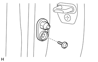
(a) Using a T30 "TORX" socket wrench, remove the screw. (b) Disconnect the connector and remove the rear door courtesy switch. |
 ).
Was this page helpful?