Installation
1. INSTALL NO. 1 MANIFOLD CONVERTER INSULATOR
(a) Install the No. 1 manifold converter insulator to the exhaust manifold converter sub-assembly with the 4 bolts. Torque: 12 N·m {122 kgf·cm, 9 ft·lbf} |
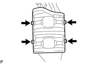 |
2. INSTALL NO. 2 EXHAUST MANIFOLD HEAT INSULATOR
(a) Install the No. 2 exhaust manifold heat insulator to the exhaust manifold converter sub-assembly with the 2 bolts. Torque: 12 N·m {122 kgf·cm, 9 ft·lbf} |
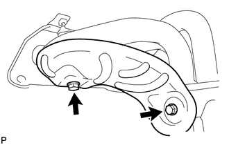 |
3. INSTALL EXHAUST MANIFOLD CONVERTER SUB-ASSEMBLY
(a) Install a new gasket onto the cylinder head sub-assembly. |
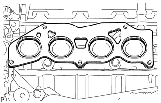 |
(b) Temporarily install the exhaust manifold converter sub-assembly to the cylinder head sub-assembly with the 5 nuts. |
 |
(c) Tighten the 5 nuts in the order shown in the illustration.
Torque:
35 N·m {357 kgf·cm, 26 ft·lbf}
4. INSTALL NO. 1 EXHAUST MANIFOLD HEAT INSULATOR
(a) Install the No. 1 exhaust manifold heat insulator to the exhaust manifold converter sub-assembly with the 4 bolts. Torque: 12 N·m {122 kgf·cm, 9 ft·lbf} |
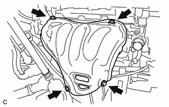 |
5. INSTALL NO. 2 MANIFOLD STAY
(a) Install the No. 2 manifold stay to the exhaust manifold converter sub-assembly and stiffening crankcase assembly with the bolt and nut. Torque: 43 N·m {438 kgf·cm, 32 ft·lbf} |
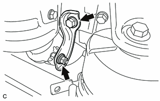 |
6. INSTALL MANIFOLD STAY
(a) Install the manifold stay to the exhaust manifold converter sub-assembly and stiffening crankcase assembly with the bolt and nut. Torque: 43 N·m {438 kgf·cm, 32 ft·lbf} |
 |
7. INSTALL AIR FUEL RATIO SENSOR

8. INSTALL FRONT EXHAUST PIPE ASSEMBLY
(a) Using a vernier caliper, measure the free length of the compression spring. Minimum Free Length: 41.5 mm (1.63 in.) If the length is less than the minimum, replace the compression spring. |
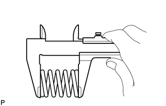 |
(b) Temporarily install a new gasket to the exhaust manifold converter sub-assembly.
(c) Using a plastic hammer and wooden block, tap in the gasket until its surface is flush with the exhaust manifold converter sub-assembly. Text in Illustration
NOTICE:
|
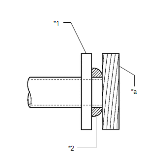 |
(d) Install a new gasket to the center exhaust pipe assembly.
(e) Install the front exhaust pipe assembly to the exhaust manifold converter sub-assembly and center exhaust pipe assembly with the 2 compression springs and 4 bolts. Torque: 43 N·m {438 kgf·cm, 32 ft·lbf} |
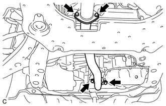 |
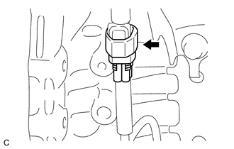
(f) Connect the heated oxygen sensor connector. |
 |
9. INSPECT FOR EXHAUST GAS LEAK
10. INSTALL NO. 2 ENGINE UNDER COVER
11. INSTALL NO. 1 ENGINE UNDER COVER
Test yourself
A quick Toyota Venza quiz: every answer comes with an explanation and a link to the manual page.