Purge Valve
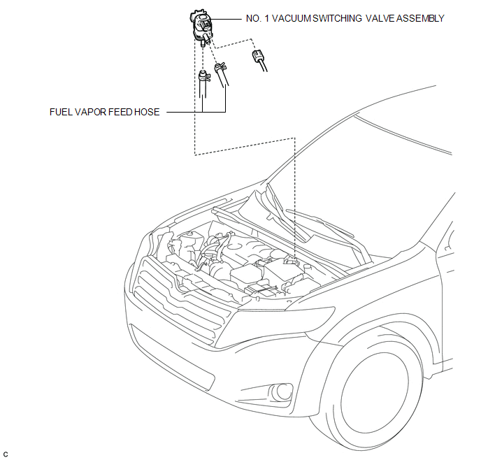
Inspection INSPECTION PROCEDURE
1. INSPECT NO. 1 VACUUM SWITCHING VALVE ASSEMBLY
(a) Measure the resistance according to the value(s) in the table below. Standard Resistance:
If the result is not as specified, replace the No. 1 vacuum switching valve assembly. |
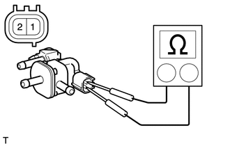 |
(b) Check the operation of the No. 1 vacuum switching valve assembly.
(1) Check that air does not flow from port F when air is applied to port E. Text in Illustration
|
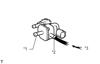 |
(2) Apply battery voltage to the connector, and check the VSV operation. Text in Illustration
OK:
If the result is not as specified, replace the No. 1 vacuum switching valve assembly. |
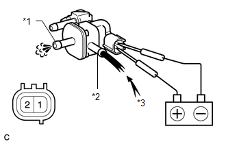 |
1. REMOVE NO. 1 VACUUM SWITCHING VALVE ASSEMBLY
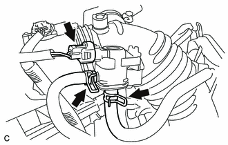
(a) Disconnect the connector and 2 fuel vapor feed hoses. |
 |
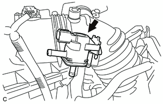
(b) Remove the No. 1 vacuum switching valve assembly. |
 |
1. INSTALL NO. 1 VACUUM SWITCHING VALVE ASSEMBLY
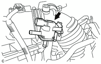
(a) Install the No. 1 vacuum switching valve assembly. |
 |
(b) Connect the connector and 2 fuel vapor feed hoses. |
 |
Test yourself
A quick Toyota Venza quiz: every answer comes with an explanation and a link to the manual page.