4- cylinder injection engine(1.4 1 direct inction. turbocharger)
Assembly overview - pistons and conrods
In this manual: 4- cylinder injection engine(1.4 1 direct inction. turbocharger)
~2min read
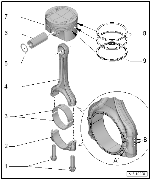
| 1 - | Bolts |
Renew
Oil threads and contact surface
30 N·m + 90°
| 2 - | Conrod bearing cap |
Mark allocation to cylinder and conrod in colour -B-.
Installation position: Lug -A- on conrod bearing cap faces towards pulley end
| 3 - | Bearing shells |
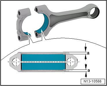
Installation position → Fig.
Renew worn bearing shells
Ensure secure seating
| 4 - | Conrod |
With industrially cracked conrod bearing cap
Renew as set only.
Mark allocation to cylinder and conrod bearing cap in colour -B-.
Measuring radial clearance → Chapter
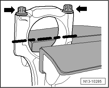
Separate new conrod → Fig..
Installation position: Lug -A- on conrod bearing cap faces towards pulley end
| 5 - | Circlip |
Qty. 2
Renew
| 6 - | Piston pin |
Removing and installing → Chapter „Removing and installing pistons“
| 7 - | Piston |
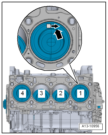
Mark installation position and cylinder number → Fig..
Removing and installing → Chapter
Checking piston and cylinder bore → Chapter
| 8 - | Piston rings |
Compression rings
Measuring ring gap → Fig.
Measuring ring-to-groove clearance → Fig.
Use commercially available piston ring pliers to remove and install.
Installation position: marking “TOP” or side with lettering towards piston crownOffset gaps by 120°.
| 9 - | Piston ring |
Oil scraper ring
Measuring ring gap → Fig.
Measuring ring-to-groove clearance → Fig.
Use piston ring pliers to remove and install.
Installation position: marking “TOP” or side with lettering towards piston crownOffset gap 120° relative to lower compression ring
Installation position and allocation of piston to cylinderArrow on piston crown points to pulley end -arrow-. |
 |
Bearing shells - installation position
Dimension -a- = 2.5 mm. |
 |
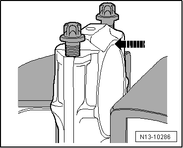
Separating new conrodsOn new conrods it is possible that the breaking point is not fully separated. When the conrod bearing cap cannot be removed by hand, proceed as follows:
Clamp conrod below dashed line.
|
 |
|
 |
Test yourself
A quick Volkswagen Golf quiz: every answer comes with an explanation and a link to the manual page.
Was this page helpful?