Note Removal and installation are described for the left side. Removal and installation on the right side are carried out in the same way.
Caution
Work on LED modules should be performed only at designated ESD workplaces.
Removing
Remove headlight → Chapter.
Using a hammer, carefully release housing cover -1- along predetermined breaking line -2-.
Remove housing cover -1- from headlight.
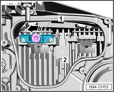
For fine adjustment, unscrew bolt -1- completely from bracket -2--arrow-.
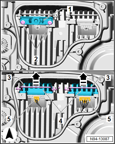
Remove bolts -2-.
Remove bracket -1-.
Release connectors -5- and pull off.
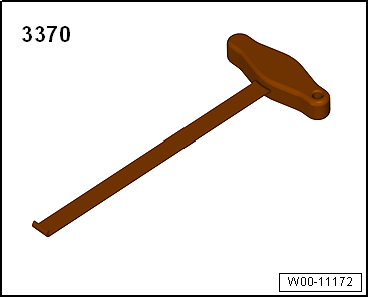
Using front-end hook -3370-, pull retaining clip -3- slightly towards rear to release.
At the same time, swing retaining clip -3- upwards -arrows-.
Remove LED modules for dipped beam headlight -4- towards rear from headlight.
Installing
WARNING
Avoid any skin contact with the heat-conductive paste!
If heat-conductive paste did get onto the skin, clean the affected area thoroughly using soap solution, for example.
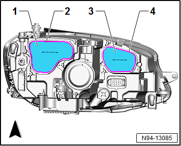
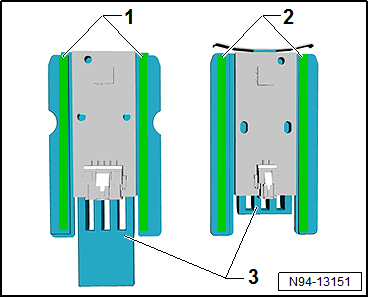
Apply a thin coat of heat-conductive paste -1- and -2- ( → Electronic Parts Catalogue “ETKA”) at side contact surfaces of LED modules -3-.
Note Make sure not to interchange the LED modules. Due to their shape, LED modules can only be installed at position given.
Insert LED modules for dipped beam headlight -4- into headlight, and fit them in installation position.
Swing retaining clips -3- downwards in opposite -direction of arrows-, and engage them audibly.
Fit connectors -5-.
Install bracket -1-, and tighten bolts -2-.
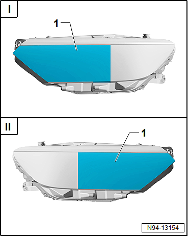
Position template -1- ( → Electronic Parts Catalogue “ETKA”) relative to contour on headlight lens, and fix it in place.
I -
Alignment of template -1- on front left headlight -MX1-
II -
Alignment of template -1- on front right headlight -MX2-
Position headlight in horizontal position at a distance of 3 to 5 m in front of a white wall.
Turn lateral adjustment screws on outside at top of headlight to stop:
Turn towards right on front left headlight -MX1- (clockwise)
Turn towards left on front right headlight -MX2- (anticlockwise)
Connect connector for headlight in vehicle and connector on removed headlight using adapter cable.
Switch on light via rotary light switch -EX1-.
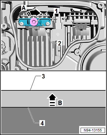
Fine adjustment on front left headlight -MX1-
For fine adjustment, slowly screw in bolt -1- on bracket -2--arrow A-.
This will cause the brighter area -4- at bottom to travel upwards slowly -arrow B-.
Continue to slowly screw in bolt -1--arrow A- until the upper edge -4- of the brighter area and the upper edge -3- of the darker area line up with each other.
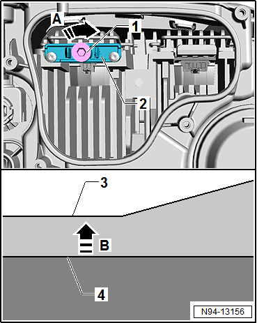
Fine adjustment on front right headlight -MX2-
For fine adjustment, slowly screw in bolt -1- on bracket -2--arrow A-.
This will cause the brighter area -4- at bottom to travel upwards slowly -arrow B-.
Continue to slowly screw in bolt -1--arrow A- until the upper edge -4- of the brighter area and the horizontal edge -3- of the darker area line up with each other.
The darker area must remain visible on the right from the inflexion point.
Continued for both headlights
Caution
Risk of damage to the headlight.
Make sure the housing cover is correctly seated when installing. The ingress of water will lead to permanent damage to the headlight.
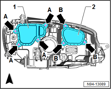
Fit new housing cover -1- onto headlight.
Screw in and tighten bolts -arrows A-.
Install headlight → Chapter.
Check headlight setting and adjust headlight if necessary → Booklet36.1
Specified torques
→ Chapter „Assembly overview - LED headlights“
?
Test yourself
A quick Volkswagen Golf quiz: every answer comes with an explanation and a link to the manual page.
 Note Removal and installation are described for the left side. Removal and installation on the right side are carried out in the same way.
 Caution
 WARNING