Mobile Online Services
General Information
Mobile Online Services are only available with a Radio/RNS -RX1-.In vehicles with a telephone, the telephone function is integrated in the Control Module For Emergency Call Module And Communication Unit -J949-. The Cell Phone Operating Electronics Control Module -J412- is not installed.
TroubleshootingThe mobile online services system is capable of self-diagnosis.
For troubleshooting, use the Vehicle Diagnostic Tester in the "Guided Fault Finding" function.Note
- When there are concerns about the function, it necessary to be familiar with the Mobile Online Services functions.
- For additional information.
- Check all vehicle equipment (clock, convenience systems, etc.) after connecting the battery.
Component Location Overview - Mobile Online Services
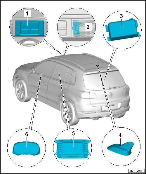
- Emergency Call Button -E276-
- Installed inside the front roof console
- Removing and installing.
- Telephone Microphone -R38-
- Installed inside the front roof console
- Removing and installing.
- Control Module for Emergency Call Module and Communication Unit -J949-
- Installed below front right seat
- Removing and installing.
- Telephone/Navigation System/Parking Heater Antenna -R66-
- Designed as a roof antenna
- Radio/RNS -RX1-
- Additional information.
- Instrument Cluster Control Module -J285-
Control Module for Emergency Call Module and Communication Unit -J949-, Removing and Installing
Removing
The Control Module for Emergency Call Module and Communication Unit -J949- is installed under the right front seat.
- Move the right front seat into its highest position and the move it all the back.
- Turn off the ignition and all electrical consumers and remove the key.
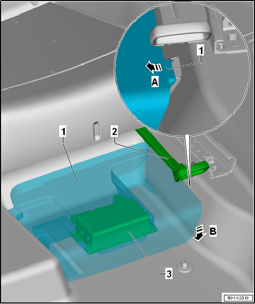
- Pull the lever -2- for seat forward/backward adjustment up and hold it.
- Push the module carrier -1- for the Cell Phone Operating Electronics Control Module -J949--3- toward the outside in direction of -arrow A- and lift it on the tunnel in direction of -arrow B-.
- Tilt the module carrier -1- for the Cell Phone Operating Electronics Control Module -J949--3- out of the outer mount.
- Turn the module carrier -1- for the Cell Phone Operating Electronics Control Module -J949--3- around.
- Release and disconnect the connectors -3 and 4- on the Cell Phone Operating Electronics Control Module -J949--2-.
- Remove the Cell Phone Operating Electronics Control Module -J949--2- from the module carrier -1-.

Installing
Install in reverse order of removal.
Emergency Call Button -E276-, Removing and Installing
Removing
- Turn off the ignition and all electrical equipment.
- Unclip the cover on the roof console -arrows-.
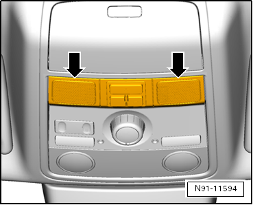
- Fold the cover down in the direction of -arrow-.

- Remove the bolts -arrows-.
- Remove the roof console section and turn it around.
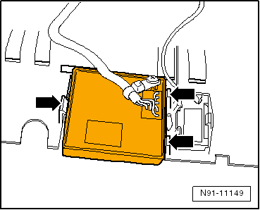
- Press the hooks -arrows -and remove the emergency call button.

- Disconnect the connector in the wire to the emergency call button.
Installing
Install in reverse order of removal.
Special Tools
Special tools and workshop equipment required
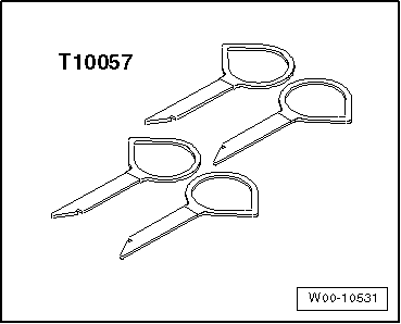
- Radio Removal Tool -T10057-
- Vehicle Diagnosis System - Updated Cable - 3m -VAS5051/5a- or Vehicle Diagnosis System - Diagnostic Cable -VAS5051/6a- or Vehicle Diagnostic Tester - Diagnostic Cable - 5m -VAS5052/3-
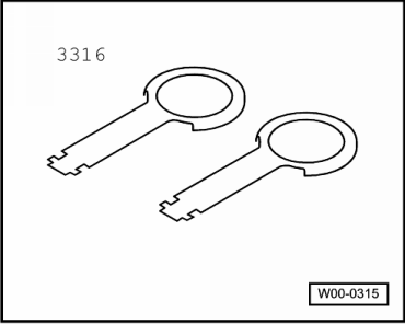
- Radio Removal Tool -3316-
- Trim Removal Wedge -3409-

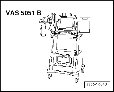
- Vehicle Diagnostic Tester
Edition: K0059110921 - RF - 04/14/2015 - JLH
Test yourself
A quick Volkswagen Tiguan quiz: every answer comes with an explanation and a link to the manual page.