Antenna Systems, RCD 300, 500 RNS 300 and Premium 7
General Information
Antenna System.
- Vehicles without radio have no rear window antenna and a "dummy" antenna without any connections is installed on the roof.
- "RCD 300", "RCD 310" and "RCD 500" radios have a rear window antenna with a right antenna amplifier as well as a roof antenna with antenna mast. One diversity function circuit runs via the rear window antenna, the second via the roof antenna.
- If the vehicle is equipped with a radio and also telephone equipment or auxiliary heating remote control, antenna system has rear window antenna with 2 trap circuits and diversity as well as a roof antenna.
- The "RNS 300" radio navigation system has a rear window antenna with a right antenna amplifier and a roof antenna.
- Vehicles with "RNS 510" radio/navigation system always have a rear window antenna with 2 trap circuits and diversity and a roof antenna, regardless of additional equipment.
Note
- Familiarity with the function and operation of the communication systems is needed if there are customer concerns.
- Refer to the Owner's Manual.
- When the battery is reconnected, check any affected system or component (radio, clock, comfort electrical connection etc.) according to the repair manual and/or the Owner's Manual.
Overview - Antenna System for Radios without Telephone/Remote Start Auxiliary Heater

- Antenna -R11-
- Roof antenna with antenna mast for FM/AM radio reception
- Install on the rear of the roof
- Antenna Amplifier 2 -R111-
- Removing and installing.
- Rear Window with One Antenna Connection
- Only for FM radio reception
- FM Frequency Filter in Positive Wire -R179-
- Installed in wiring harness
- Its function is to prevent antenna signals from shorting to ground
- Connection Point as Frequency Filter Set
- Because there is no AM radio reception via the rear window antenna, no amplitude modulation (AM) frequency filter is required. Therefore, there is only one connection point for rear window defroster voltage distribution here.
- Rear Window Defroster Voltage Distribution, Negative
- Rear Window Defroster Voltage Distribution, Positive
- FM Frequency Filter in Negative Wire -R178-
- Installed in wiring harness
- Its function is to prevent antenna signals from shorting to ground
- Radio -R-
- "RCD 500" radio
- Two antenna wires for FM/AM Antenna selection (diversity) in radio
- Radio -R-
- "RCD 300" Radio
- "Premium 7" Radio
- Two antenna wires for FM/AM Antenna selection (diversity) in radio
Overview - Antenna System for Radios and Radio Navigation Systems with Telephone/Remote Start Auxiliary Heater

- Antenna -R11-
- Roof antenna for navigation, telephone and auxiliary heater remote ignition
- Install on the rear of the roof
- Removing and installing.
- Auxiliary Heater Remote Start Antenna Connection
- Connection for Cellular Telephone -R54-
- Antenna Selection Control Module -J515-
- Only installed in conjunction with the Radio/Navigation Display Control Module -J503-"RNS MFD 2" with CD drive
- Antenna Amplifier -R24-
- For FM reception
- Removing and installing.
- Antenna Amplifier 2 -R111-
- For FM and AM reception
- Removing and installing.
- Rear Window with Two Antenna Connectors
- For FM and AM radio reception
- FM Frequency Filter in Positive Wire -R179-
- Installed in wiring harness
- Its function is to prevent antenna signals from shorting to ground
- AM Frequency Filter -R177-
- Installed in the rear lid
- Its function is to prevent antenna signals from shorting to ground
- Removing and installing.
- Antenna Amplifier 2 -R111-
- For FM and AM reception
- Removing and installing.
- Rear Window with One Antenna Connection
- For FM and AM radio reception
- FM Frequency Filter in Positive Wire -R179-
- Installed in wiring harness
- Its function is to prevent antenna signals from shorting to ground
- AM Frequency Filter -R177-
- Installed in the rear lid
- Its function is to prevent antenna signals from shorting to ground
- Rear Window Defroster Voltage Distribution, Negative
- Rear Window Defroster Voltage Distribution, Positive
- FM Frequency Filter in Negative Wire -R178-
- Installed in wiring harness
- Its function is to prevent antenna signals from shorting to ground
- Rear Window Defroster Voltage Distribution, Negative
- Rear Window Defroster Voltage Distribution, Positive
- FM Frequency Filter in Negative Wire -R178-
- Installed in wiring harness
- Its function is to prevent antenna signals from shorting to ground
- Radio -R-
- "RCD" radio" "
- With only one antenna wire for AM/FM radio reception, without diversity function
- Radio -R-
- "RCD 300" Radio
- Two antenna wires for FM/AM Antenna selection (diversity) in radio
- Radio -R-
- "RCD 300" Radio
- Two antenna wires for FM/AM Antenna selection (diversity) in radio
- Radio/Navigation Display Unit Control Module -J503-
- "RNS 300" Radio Navigation System
- With only one antenna wire for AM/FM radio reception, without diversity function
- With one antenna wire to roof antenna for navigation
- Radio/Navigation Display Unit Control Module -J503-
- Radio Navigation System "RNS 510" with DVD drive
Overview - Antenna System with Digital Satellite Tuner

- Satellite Tuner Antenna -R172-
- Located on the roof at the back of the vehicle
- Depending on equipment, responsible for navigation, telephone, satellite reception and auxiliary heater remote start
- From 11/06 only one antenna wire between satellite tuner and tuner antenna
- Removing and installing. Refer
- Auxiliary Heater Remote Operation (Remote Start) Antenna Line
- Digital Satellite Radio Tuner -R190-
- Installed below front right seat
- From 11/06 only one antenna wire between satellite tuner and tuner antenna
- Removing and installing.
- Antenna Amplifier -R24-
- For FM reception
- Removing and installing.
- Antenna Amplifier 2 -R111-
- For FM/AM reception
- Removing and installing.
- Radio/Navigation Display Unit Control Module -J503-
- Here "RNS 510"
- Radio -R-
- Here "Premium Sound System"
- FM Frequency Filter in Positive Wire -R179-
- Installed in wiring harness
- Its function is to prevent antenna signals from shorting to Ground
- AM Frequency Filter -R177-
- Installed in rear lid, center
- Its function is to prevent antenna signals from shorting to ground
- Removing and installing.
- FM Frequency Filter in Negative Wire -R178-
- Installed in wiring harness
- Its function is to prevent antenna signals from shorting to ground
- Rear Window Antenna 1 -R130-
- Telephone System
Left/Right Antenna Module -R108-/-R109- in the Rear Lid, Removing and Installing
There are two antenna amplifiers. They are installed at left and right of rear lid near rear window.
Removal and installation on left and right is identical.
Removing
Note
Removing and installing on the left and right sides is identical.
Perform the following steps before starting:
- Turn off the ignition and all electric consumers and remove the key.
It is necessary to remove the rear lid trim panel first in order to be able to remove the antenna module.
- Disconnect the connectors on the antenna module.
- Remove the screw -arrow-.

- Move the antenna module in direction of -arrow- to the right and remove it from the rear lid.

Installing
Install in reverse order of removal.
When installing, ensure amplifier is remounted on the locations where it was mounted before it was removed.
AM Frequency Filter, Removing and Installing
Removing
Amplitude modulation (AM) frequency filter is installed at left in the rear lid in Tiguan.Its function is to prevent antenna signals from shorting to ground
Perform the following steps before starting:- Turn off the ignition and all electric consumers and remove the key.
The rear lid trim panel must be removed first in order to be able to replace the AM frequency filter.
- Remove the red circlip -1- in direction of -arrow- from the connector housing. Press the release -2- and disconnect the connector.
- Do the same with the other two connectors.

- Remove the 3 screws -arrows- and remove the frequency filter.

Installing
Install in reverse order of removal.
Frequency Filter, FM, Removing and Installing
Removing
Note
Removing and installing on the left and right sides is identical.
Perform the following steps before starting:
- Turn off the ignition and all electric consumers and remove the key.
It is necessary to remove the rear lid trim panel first in order to be able to remove the frequency filter.
- Disconnect the connectors on the frequency filter.
Mounting -arrow- on the frequency filter

- Carefully pry out the frequency filter with a screwdriver -arrow-.
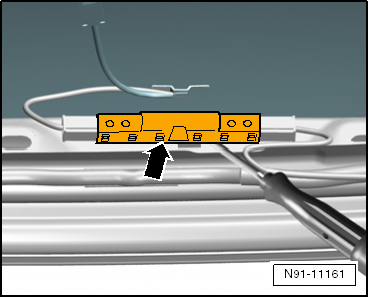
Installing
- Push the frequency filter into the opening -arrow- until it engages.

Install in reverse order of removal.
Antenna Selection Control Module, Removing and Installing
Removing
Do the following before starting the procedure:
- Turn off the ignition and all electric consumers and remove the key.
- Move the right front seat as far back as possible.
- Remove cover under seat in direction of -arrow-.

- Release and disconnect electrical connection -A-.

- Remove clips -arrows- and remove control module.

Installing
Install in reverse order of removal.
Roof Antenna
Removing
Note
- The roof antenna is available in the following versions: "navigation only", "telephone only", "satellite radio only" or "navigation, telephone and satellite radio".
- There are different versions of the roof antenna: "navigation only", "telephone only", "navigation and telephone" or "navigation, telephone and parking heater remote control".
- The roof antenna is available in "dummy", "shark fin" or "16V antenna" designs.
- The following procedure describes the "shark fin" roof antenna. The procedure is similar for the "dummy" and "16V antenna" designs.
- Remove the roof end molding.
- Loosen the C-pillar trim panels near the headliner.
- Lower the headliner.
- Remove the nut -2-.

- Disengage connectors -arrows-, disconnect them and remove roof antenna.

Note
- Depending on antenna version, there may be up to 3 connectors here.
- Connector with violet housing is telephone wire connection.
- The connector with the blue housing is the navigation system wiring connection.
- The third possibility is a connector for the auxiliary heater remote control.
Installing
Install in reverse order of removal.
Note
- When inserting roof antenna, ensure gasket is properly seated. Both guide protrusions of the seal must be seated in the appropriate holes -arrows- in antenna base.

- When inserting roof antenna, make sure antenna wires -1- are routed correctly through the wire pass-through in the nut -2-.

Antenna Wires, Replacing
All Instructions and Information on This Chapter Can Be Found in the "Electrical Equipment General Information" Repair Manual.
Test yourself
A quick Volkswagen Tiguan quiz: every answer comes with an explanation and a link to the manual page.