Karosserie-Elektrik
Anzeigen und Instrumente
In diesem Handbuch: Karosserie-Elektrik
43Schritte
~258Min.
4/5Schwierigkeit
Erledigt 0 von 43
Inhalt:
Fehlersuche Kombiinstrument
Fehlerbehebung
TFT-LCD-Display schaltet sich nicht ein
| Prüfliste | Detailprüfungen | Bauteile |
|
|
Steckverbinder, Kabelbaum, Sicherungen, Kombiinstrument |
Störung der Airbag-Warnleuchte
| Prüfliste | Detailprüfungen | Bauteile |
|
|
ACU-Steckverbinder, Kabelbaum, Sicherungen, Kombiinstrument |
Störung des integrierten Fahrmodus
| Prüfliste | Detailprüfungen | Bauteile |
|
|
Schalterstecker, Kabelbaum, Kombiinstrument |
Kein Alarm
| Prüfliste | Detailprüfungen | Bauteile |
|
|
Lautsprecherstecker, Kabelbaum, Kombiinstrument |
Fehlerhafte Kraftstoffanzeige
| Prüfliste | Detailprüfungen | Bauteile |
|
|
Kraftstoffgeber-Stecker, Kabelbaum, Kombiinstrument |
Kombiinstrument-Prüfung am Fahrzeug
Fahrzeugprüfung
Sichtprüfung
- Prüfpunkt (Warnleuchte)
Informationen zu Störungszuständen und normalen Betriebszuständen finden Sie in der Betriebsanleitung.
Nein Abbildung Bezeichnung Farbe Signaleingang Signalsteuerung
(Steuergerät/Sensor)Prüfpunkt 1 
Blinker (links) Grün CAN IBU
(Gateway)- Multifunktionsschalter
- IBU
- CAN-Fehler
2 
Blinker (rechts) Grün CAN IBU
(Gateway)- Multifunktionsschalter
- IBU
- CAN-Fehler
3 
Schlussleuchte Grün CAN IBU
(Gateway)- Multifunktionsschalter
- IBU
- CAN-Fehler
4 
Frontnebelscheinwerfer Grün CAN IBU
(Gateway)- Multifunktionsschalter
- IBU
- CAN-Fehler
5 
Hintere Nebelleuchte Gelb CAN IBU
(Gateway)- Multifunktionsschalter
- IBU
- CAN-Fehler
6 
Fernlicht Blau CAN IBU
(Gateway)- Multifunktionsschalter
- IBU
- CAN-Fehler
7 
Abblendlicht Grün CAN IBU
(Gateway)- Multifunktionsschalter
- IBU
- CAN-Fehler
8 
High Beam Assist (HBA) Grün CAN LKA - HBA-System
- CAN-Fehler
9 
LED-Scheinwerfer Gelb CAN IBU
(Gateway)- IBU
- CAN-Fehler
10 
Warnung Gelb CAN BCW - BCW-System
- CAN-Fehler
TPMS - TPMS-System
- CAN-Fehler
FCA - FCA-System
- CAN-Fehler
IBU - Außenbeleuchtung
- IBU
- CAN-Fehler
Festverdrahtet Kraftstoffgeber - Störung Kraftstoffgeber
- Leitungsfehler
Scheibenwaschwasser niedrig - Scheibenwaschwasser-Füllstandssensor
- Leitungsfehler
Digitaler Eingang Erinnerung an Serviceprüfungen
(Inspektionsintervall)11 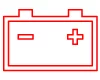
LADEN Rot CAN ECM - ECM
- CAN-Fehler
12 
Öldruck Rot CAN ECM - Öldrucksensor
- Festverdrahtet
- ECM
- CAN-Fehler
13 
Motor Gelb CAN ECM - ECM
- IBU
- CAN-Fehler
14 
Wegfahrsperre Gelb CAN ECM
IBU
(Gateway)- SMK-System
- IBU
- CAN-Fehler
- Festverdrahtet
15 
Feststellbremse
Bremsflüssigkeit
EBDRot CAN
FestverdrahtungIBU
(Gateway)
EBD
ABS
TCS- IBU
- ABS-System
- CAN-Fehler
- Feststellbremsschalter
- Sensor Bremsflüssigkeitsstand
16 
ABS Gelb CAN ABS - ABS-System
- CAN-Fehler
17 
Elektronisches Stabilitätsprogramm (ESC) Gelb CAN TCS - TCS-System
- CAN-Fehler
18 
Elektronische Stabilitätskontrolle (ESC) AUS Gelb CAN TCS - TCS-System
- CAN-Fehler
19 
Elektronische Parkbremse (EPB) Gelb CAN EPB - EPB-System
- CAN-Fehler
20 
Wenn der Sicherheitsgurt nicht angelegt ist Rot CAN IBU
(Gateway)- IBU
- CAN-Fehler
21 
Auto Hold Weiß
Gelb
GrünCAN VDC - TCS-System
- CAN-Fehler
22 
Airbag Rot CAN SRSCM - SRSCM-System
- CAN-Fehler
23 
MDPS Rot CAN MDPS - MDPS-Steuergerät-System
- MDPS-Motor
- CAN-Fehler
24 
Reifendruck-Kontrollsystem (TPMS) Gelb CAN TPMS - TPMS-System
- TPMS-Sensor
- CAN-Fehler
25 
Kraftstoffwarnung Gelb Direkt
(Micom)Kraftstoffsegment - Störung Kraftstoffgeber
- Leitungsfehler
26 
Autonome Notbremsung (AEB) Gelb CAN SCC 1) ECM-System
2) CAN-Störung27 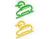
DBC Grün
GelbCAN TCS 1) DBC-System
2) CAN-Störung28 
4WD-Sperre Grün CAN 4WD-Steuergerät - 4WD-System
- CAN-Fehler
- Prüfpunkt (Anzeige)
NEIN Bezeichnung Signaleingang Signalsteuerung Prüfpunkt 1 Geschwindigkeitsmesser C-CAN ABS / ESC - CAN-Leitungsstörung
2 Drehzahlmesser C-CAN EMS - CAN-Leitungsstörung
3 Kraftstoffstand Festverdrahtung Kraftstoffgeber - Störung Kraftstoffgeber
- Festverdrahtungsstörung
Diagnose mit KDS
- Probleme des Kombiinstruments können mit dem KDS schneller diagnostiziert werden (siehe „DTC-Leitfaden“).
- Eigendiagnose: Den Diagnose-Fehlercode (DTC) mit dem KDS auslesen. (Bei gefundenem Fehlercode den DTC-Leitfaden heranziehen.)
- SW-Verwaltung: Steuerung weiterer Funktionen, einschließlich Einstellung der Systemoptionen und Nullpunktabgleich. (SW-Verwaltung → Cluster Module → CLU-Varianten-Codierung) (SW-Verwaltung → Cluster Module → Kilometerstand einstellen)
|
Funktion der Kombiinstrument-Klemmen
Steckverbinder- und Klemmenfunktionen
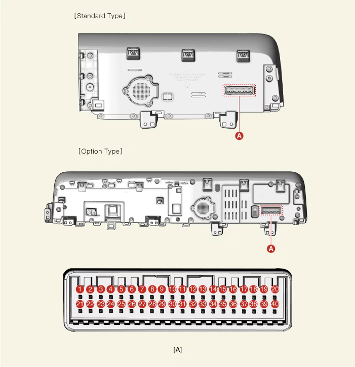
| Klemme | Stecker A | ||
| Funktion | Klemme | Funktion | |
| 1 | Masse | 21 | Eingang Trip-Schalter (-) |
| 2 | Beleuchtung (-) | 22 | Eingang Trip-Schalter 1 (+) |
| 3 | Eingang Rheostat-Schalter (abwärts) | 23 | Eingang Trip-Schalter 2 (+) |
| 4 | Eingang Rheostat-Schalter (aufwärts) | 24 | Eingang Griffsteuerschalter (+) |
| 5 | Raststellung | 25 | Eingang Griffsteuerschalter (-) |
| 6 | AT (Stellung „P“) | 26 | - |
| 7 | AT (Stellung „R“) | 27 | - |
| 8 | AT (Stellung „N“) | 28 | - |
| 9 | AT (Stellung „D“) | 29 | M-CAN (Low) |
| 10 | AT (Stellung „S“) | 30 | M-CAN (High) |
| 11 | - | 31 | - |
| 12 | Fahrzeuggeschwindigkeit (Ausgang) | 32 | C-CAN (High) |
| 13 | Lichtmaschine (Eingang) | 33 | C-CAN (Low) |
| 14 | Kraftstoffgeber ( + ) (Eingang) | 34 | - |
| 15 | - | 35 | - |
| 16 | Kraftstoffgeber ( - ) (Eingang) | 36 | - |
| 17 | - | 37 | Masse |
| 18 | Airbag-Warnleuchte | 38 | - |
| 19 | Öldruckschalter (Eingang) | 39 | IG 1 |
| 20 | - | 40 | Batterie (+) |
Kombiinstrument aus- und einbauen
Ausbau
[Standardtyp]- Den negativen Batteriepol (–) abklemmen.
- Zierblende der Armaturentafel-Mitte ausbauen. (Siehe Karosserie – „Zierblende Armaturentafel“)
- Vorderes mittleres Lautsprechergitter ausbauen.
- Vorderes mittleres Lautsprechergitter (A) mit dem Lösewerkzeug ausbauen.
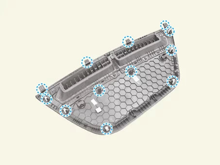
Position der Clips :
- Steckverbinder des Automatik-Lichtsensors (A) abziehen.
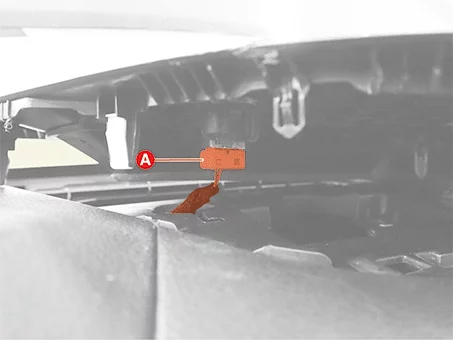
- Vorderes mittleres Lautsprechergitter (A) mit dem Lösewerkzeug ausbauen.
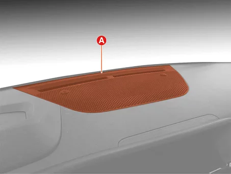
- Die Abdeckung des Head-up-Displays (HUD) (A) mit dem Hebelwerkzeug abnehmen.
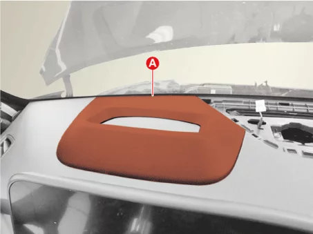

Position der Clips : - Nach dem Lösen der Schrauben das Kombiinstrument (A) ausbauen.
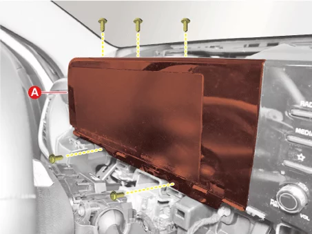
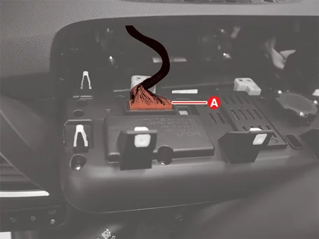
- Die Steckverbinder des Kombiinstruments (A) abziehen.
- Den negativen Batteriepol (–) abklemmen.
- Mittlere Luftdüse ausbauen. (Siehe Karosserie - „Armaturenbrett-Luftdüse“)
- Vorderes mittleres Lautsprechergitter ausbauen.
- Vorderes mittleres Lautsprechergitter (A) mit dem Lösewerkzeug ausbauen.
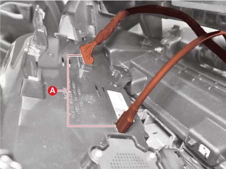
Position der Clips : - Steckverbinder des Automatik-Lichtsensors (A) abziehen.
- Vorderes mittleres Lautsprechergitter (A) mit dem Lösewerkzeug ausbauen.
- Die Abdeckung der Head-up-Display-Einheit (HUD) (A) abnehmen.
Position der Clips : - Mittelkonsole oberes Blendteil (A) mit dem Lösewerkzeug ausbauen.
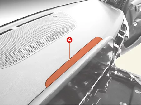
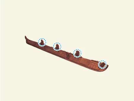
Position der Clips : - Nach dem Lösen der Befestigungsschrauben das Kombiinstrument (A) ausbauen.
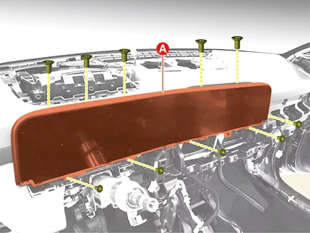
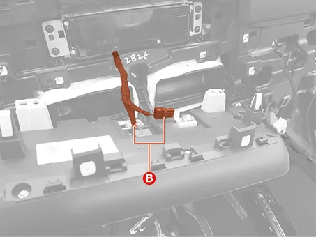
- Den Steckverbinder des Kombiinstruments (A), (B) abziehen.
Einbau
- Einbau in umgekehrter Reihenfolge des Ausbaus.
- Beim Austausch des Kombiinstruments die folgenden Schritte mit dem KDS durchführen. (S/W Management → Cluster Module → CLU Variant Coding) (S/W Management → Cluster Module → Setting mileage)
Betriebsbedingungen und Details siehe KDS-Anzeige.
War diese Seite hilfreich?