Body Electrical System
Indicators And Gauges
In this manual: Body Electrical System
43steps
~258min
4/5difficulty
Done 0 of 43
Contents:
Cluster Troubleshooting
Troubleshooting
TFT - LCD Screen Does Not Turn On
| Check List | Detailed Inspections | Components |
|
|
Connectors, Wiring, Fuses, Instrument cluster |
Airbag Warning Lamp Malfunction
| Check List | Detailed Inspections | Components |
|
|
ACU Connectors, Wiring, Fuses, Instrument cluster |
Integrated Driving Mode Malfunction
| Check List | Detailed Inspections | Components |
|
|
Switch connector, Wiring, Instrument cluster |
No Alarm
| Check List | Detailed Inspections | Components |
|
|
Speaker connectors, Wiring, Instrument cluster |
Faulty Fuel Gauge Indication
| Check List | Detailed Inspections | Components |
|
|
Fuel sender connector, Wiring, Instrument cluster |
Cluster On Vehicle Inspection
On Vehicle Inspection
Visual Inspection
- Check point (Warning lamp)
For fault conditions and normal operating conditions, refer to the owner's manual.
No Illustration Name Color Signal Input Signal Control
(Unit/Sensor)Check Point 1 
Turn signal (Left) Green CAN IBU
(Gateway)- Multifunction Switch
- IBU
- CAN Failure
2 
Turn signal (Right) Green CAN IBU
(Gateway)- Multifunction Switch
- IBU
- CAN Failure
3 
Tail Lamp Green CAN IBU
(Gateway)- Multifunction Switch
- IBU
- CAN Failure
4 
Front Fog Lamp Green CAN IBU
(Gateway)- Multifunction Switch
- IBU
- CAN Failure
5 
Rear Fog Lamp Yellow CAN IBU
(Gateway)
- Multifunction Switch
- IBU
- CAN Failure
6 
High Beam Blue CAN IBU
(Gateway)- Multifunction Switch
- IBU
- CAN Failure
7 
Low beam Green CAN IBU
(Gateway)- Multifunction Switch
- IBU
- CAN Failure
8 
High Beam Assist (HBA) Green CAN LKA - HBA System
- CAN Failure
9 
LED Headlamp Yellow CAN IBU
(Gateway)- IBU
- CAN Failure
10 
Warning Yellow CAN BCW - BCW System
- CAN Failure
TPMS - TPMS System
- CAN Failure
FCA - FCA System
- CAN Failure
IBU - External Lamp
- IBU
- CAN Failure
Hard-wired Fuel Sender - Fuel Sender Failure
- Wiring Failure
Low Washer - Washer Fluid Level Sensor
- Wiring Failure
Digital Input Reminder for Service Checks
(Inspection Cycle)11 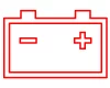
CHARGE Red CAN ECM - ECM
- CAN Failure
12 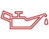
Oil Pressure Red CAN ECM - Oil Pressure Sensor
- Hard-wired
- ECM
- CAN Failure
13 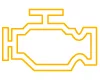
Engine Yellow CAN ECM - ECM
- IBU
- CAN Failure
14 
Immobilizer Yellow CAN ECM
IBU
(Gateway)- SMK System
- IBU
- CAN Failure
- Hard-wired
15 
Parking Brake
Brake Fluid
EBDRed CAN
Hard-wiredIBU
(Gateway)
EBD
ABS
TCS- IBU
- ABS System
- CAN Failure
- Parking Brake Switch
- Brake Oil Lever Sensor
16 
ABS Yellow CAN ABS - ABS System
- CAN Failure
17 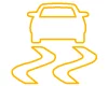
Electronic Stability Control (ESC) Yellow CAN TCS - TCS System
- CAN Failure
18 
Electronic Stability Control (ESC) OFF Yellow CAN TCS - TCS System
- CAN Failure
19 
Electronic Parking Brake (EPB) Yellow CAN EPB - EPB System
- CAN Failure
20 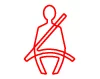
When seat belt is not fastened Red CAN IBU
(Gateway)- IBU
- CAN Failure
21 
Auto Hold White
Yellow
GreenCAN VDC - TCS System
- CAN Failure
22 
Airbag Red CAN SRSCM - SRSCM System
- CAN Failure
23 
MDPS Red CAN MDPS - MDPS Unit System
- MDPS Motor
- CAN Failure
24 
Tire Pressure Monitoring System (TPMS) Yellow CAN TPMS - TPMS System
- TPMS Sensor
- CAN Failure
25 
Fuel Warning Yellow Direct
(Micom)Fuel Segment - Fuel Sender Failure
- Wiring Failure
26 
Autonomous Emergency Braking (AEB) Yellow CAN SCC 1) ECM System
2) CAN Failure27 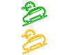
DBC Green
YellowCAN TCS 1) DBC System
2) CAN Failure28 
4WD Lock Green CAN 4WD ECU - 4WD System
- CAN Failure
- Check point (Gauge)
NO Name Signal Input Signal Control Check Point 1 Speedometer C-CAN ABS / ESC - CAN Line failure
2 Tachometer C-CAN EMS - CAN Line failure
3 Fuel level Hardwire Fuel Sender - Fuel Sender Failure
- Hardwire failure
Diagnosis with KDS
- The cluster can be more quickly diagnosed for problems with the KDS (Refer to "DTC guide").
- Self diagnosis : Inspect the Diagnostic Trouble Code (DTC) with the KDS. (Refer to DTC guide when fault code is found.)
- S/W Management : Controlling other features including system option setting and zero point adjustment. (S/W Management → Cluster Module → CLU Variant Coding) (S/W Management → Cluster Module → Setting mileage)
|
Cluster Terminal Function
Connector and Terminal Function
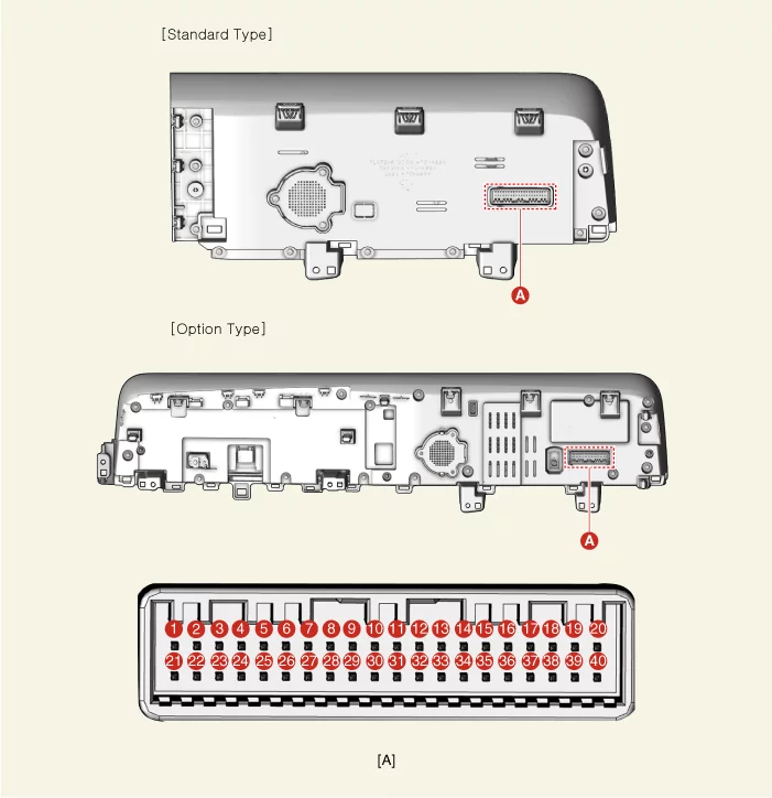
| Terminal | Connector A | ||
| Function | Terminal | Function | |
| 1 | Ground | 21 | Trip switch ( - ) input |
| 2 | Illumination ( - ) | 22 | Trip switch 1 ( + ) input |
| 3 | Rheostat switch (Down) Input | 23 | Trip switch 2 ( + ) input |
| 4 | Rheostat switch (UP) input | 24 | Grip control switch ( + ) input |
| 5 | Detent | 25 | Grip control switch ( - ) input |
| 6 | AT ('P' Position) | 26 | - |
| 7 | AT ('R' Position) | 27 | - |
| 8 | AT ('N' Position) | 28 | - |
| 9 | AT ('D' Position) | 29 | M-CAN (Low) |
| 10 | AT ('S' Position) | 30 | M-CAN (High) |
| 11 | - | 31 | - |
| 12 | Vehicle speed (output) | 32 | C-CAN (High) |
| 13 | Alternator (Input) | 33 | C-CAN (Low) |
| 14 | Fuel sender ( + ) input | 34 | - |
| 15 | - | 35 | - |
| 16 | Fuel sender ( - ) input | 36 | - |
| 17 | - | 37 | Ground |
| 18 | Airbag warning lamp | 38 | - |
| 19 | Oil press switch (Input) | 39 | IG 1 |
| 20 | - | 40 | Battery (+) |
Cluster Removal and Installation
Removal
[Standard Type]- Disconnect the negative ( - ) battery terminal.
- Remove the crash pad center garnish. (Refer to Body - "Crash Pad Garnish")
- Remove the front center speaker grille.
- Remove the front center speaker grille (A) by using the remover.
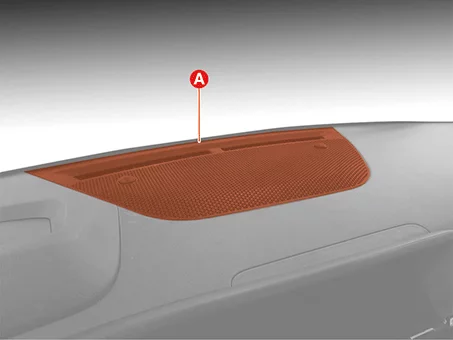
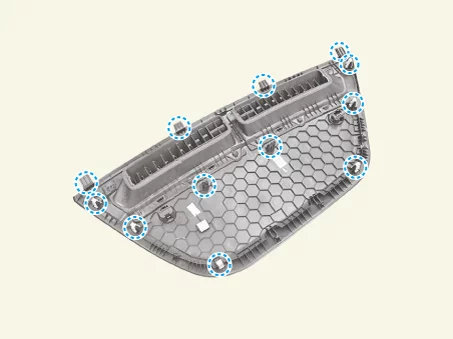
Clip position :
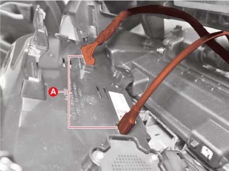
- Disconnect the auto light sensor connector (A).
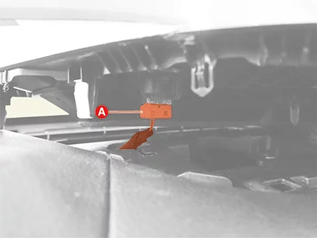
- Remove the front center speaker grille (A) by using the remover.
- Remove the Head-Up Display (HUD) cover (A) by using the remover.
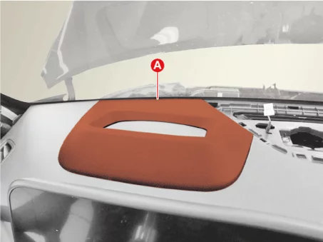

Clip position : - Remove the cluster (A) after removing the screws.
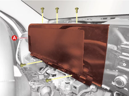
- Disconnect the cluster connectors (A).
- Disconnect the negative ( - ) battery terminal.
- Remove the center air vent. (Refer to Body - "Crash Pad Air Vent")
- Remove the front center speaker grille.
- Remove the front center speaker grille (A) by using the remover.
Clip position : - Disconnect the auto light sensor connector (A).
- Remove the front center speaker grille (A) by using the remover.
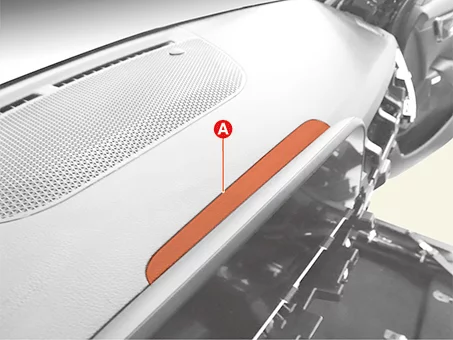
- Remove the Head-Up Display (HUD) unit cover (A).
Clip position : - Remove the center fascia upper panel (A) by using the remover.
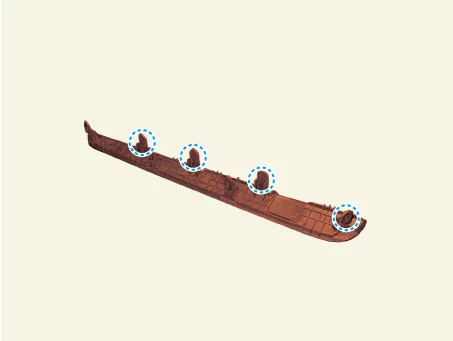
Clip position : - Remove the cluster (A) after removing the mounting screws.
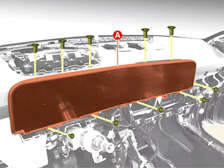
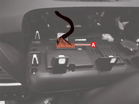
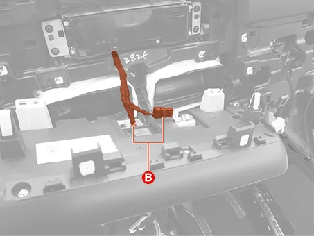
- Disconnect the cluster connector (A), (B).
Installation
- Install in reverse order of removal.
- Perform the order below with the KDS when replacing the cluster. (S/W Management → Cluster Module → CLU Variant Coding) (S/W Management → Cluster Module → Setting mileage)
Refer to the KDS screen for operating conditions and details.
Was this page helpful?