Impianto elettrico della carrozzeria
Spie e strumenti
In questo manuale: Impianto elettrico della carrozzeria
43passaggi
~258min
4/5difficoltà
Completati 0 di 43
Contenuto:
Diagnosi del quadro strumenti
Risoluzione dei problemi
Il display TFT - LCD non si accende
| Lista di controllo | Ispezioni dettagliate | Componenti |
|
|
Connettori, cablaggio, fusibili, quadro strumenti |
Malfunzionamento della spia airbag
| Lista di controllo | Ispezioni dettagliate | Componenti |
|
|
Connettori ACU, cablaggio, fusibili, quadro strumenti |
Malfunzionamento della modalità di guida integrata
| Lista di controllo | Ispezioni dettagliate | Componenti |
|
|
Connettore interruttore, cablaggio, quadro strumenti |
Nessun allarme
| Lista di controllo | Ispezioni dettagliate | Componenti |
|
|
Connettori altoparlanti, cablaggio, quadro strumenti |
Indicazione errata del livello carburante
| Lista di controllo | Ispezioni dettagliate | Componenti |
|
|
Connettore del sensore carburante, cablaggio, quadro strumenti |
Ispezione del quadro strumenti sul veicolo
Ispezione del veicolo
Ispezione visiva
- Punto di controllo (spia di avvertimento)
Per le condizioni di guasto e di funzionamento normale, consultare il manuale del proprietario.
No Illustrazione Nome Colore Ingresso segnale Controllo segnale
(Unità/Sensore)Punto di controllo 1 
Indicatore di direzione (sinistro) Verde CAN IBU
(Gateway)- Interruttore multifunzione
- IBU
- Guasto CAN
2 
Indicatore di direzione (destro) Verde CAN IBU
(Gateway)- Interruttore multifunzione
- IBU
- Guasto CAN
3 
Fanale posteriore Verde CAN IBU
(Gateway)- Interruttore multifunzione
- IBU
- Guasto CAN
4 
Fendinebbia anteriore Verde CAN IBU
(Gateway)- Interruttore multifunzione
- IBU
- Guasto CAN
5 
Fendinebbia posteriore Giallo CAN IBU
(Gateway)- Interruttore multifunzione
- IBU
- Guasto CAN
6 
Abbaglianti Blu CAN IBU
(Gateway)- Interruttore multifunzione
- IBU
- Guasto CAN
7 
Anabbagliante Verde CAN IBU
(Gateway)- Interruttore multifunzione
- IBU
- Guasto CAN
8 
Assistente abbaglianti (HBA) Verde CAN LKA - Sistema HBA
- Guasto CAN
9 
Faro LED Giallo CAN IBU
(Gateway)- IBU
- Guasto CAN
10 
Avvertenza Giallo CAN BCW - Sistema BCW
- Guasto CAN
TPMS - Sistema TPMS
- Guasto CAN
FCA - Sistema FCA
- Guasto CAN
IBU - Luci esterne
- IBU
- Guasto CAN
Cablato Trasmettitore livello carburante - Guasto del sensore carburante
- Guasto cablaggio
Livello basso liquido lavacristallo - Sensore del livello del liquido lavacristalli
- Guasto cablaggio
Ingresso digitale Promemoria per i controlli di manutenzione
(ciclo di ispezione)11 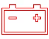
RICARICA Rosso CAN ECM - ECM
- Guasto CAN
12 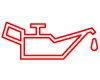
Pressione olio Rosso CAN ECM - Sensore pressione olio
- Cablato
- ECM
- Guasto CAN
13 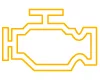
Motore Giallo CAN ECM - ECM
- IBU
- Guasto CAN
14 
Immobilizer Giallo CAN ECM
IBU
(Gateway)- Sistema SMK
- IBU
- Guasto CAN
- Cablato
15 
Freno di stazionamento
Liquido freni
EBDRosso CAN
Cablaggio direttoIBU
(Gateway)
EBD
ABS
TCS- IBU
- Sistema ABS
- Guasto CAN
- Interruttore del freno di stazionamento
- Sensore livello liquido freni
16 
ABS Giallo CAN ABS - Sistema ABS
- Guasto CAN
17 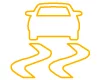
Controllo elettronico di stabilità (ESC) Giallo CAN TCS - Sistema TCS
- Guasto CAN
18 
Controllo elettronico della stabilità (ESC) disattivato Giallo CAN TCS - Sistema TCS
- Guasto CAN
19 
Freno di stazionamento elettronico (EPB) Giallo CAN EPB - Sistema EPB
- Guasto CAN
20 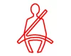
Quando la cintura di sicurezza non è allacciata Rosso CAN IBU
(Gateway)- IBU
- Guasto CAN
21 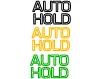
Auto Hold Bianco
Giallo
VerdeCAN VDC - Sistema TCS
- Guasto CAN
22 
Airbag Rosso CAN SRSCM - Sistema SRSCM
- Guasto CAN
23 
MDPS Rosso CAN MDPS - Sistema unità MDPS
- Motore MDPS
- Guasto CAN
24 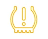
Sistema di monitoraggio della pressione dei pneumatici (TPMS) Giallo CAN TPMS - Sistema TPMS
- Sensore TPMS
- Guasto CAN
25 
Avviso carburante Giallo Diretto
(Micom)Segmento carburante - Guasto del sensore carburante
- Guasto cablaggio
26 
Frenata di emergenza autonoma (AEB) Giallo CAN SCC 1) Sistema ECM
2) Guasto CAN27 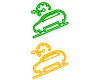
DBC Verde
GialloCAN TCS 1) Sistema DBC
2) Guasto CAN28 
Blocco 4WD Verde CAN Centralina 4WD - Sistema 4WD
- Guasto CAN
- Punto di controllo (misuratore)
NO Nome Ingresso segnale Controllo segnale Punto di controllo 1 Tachimetro C-CAN ABS / ESC - Guasto linea CAN
2 Contagiri C-CAN EMS - Guasto linea CAN
3 Livello carburante Cablaggio diretto Trasmettitore livello carburante - Guasto del sensore carburante
- Guasto cablaggio diretto
Diagnosi con KDS
- Il quadro strumenti può essere diagnosticato più rapidamente per i problemi tramite il KDS (vedere «Guida DTC»).
- Autodiagnosi: verificare i codici di guasto diagnostici (DTC) con il KDS. (Vedere la Guida DTC in presenza di un codice di guasto.)
- Gestione S/W: controllo di altre funzioni, tra cui impostazione delle opzioni di sistema e regolazione del punto zero. (Gestione S/W → Cluster Module → CLU Variant Coding) (Gestione S/W → Cluster Module → Impostazione chilometraggio)
|
Funzione dei terminali del quadro strumenti
Funzione di connettori e terminali
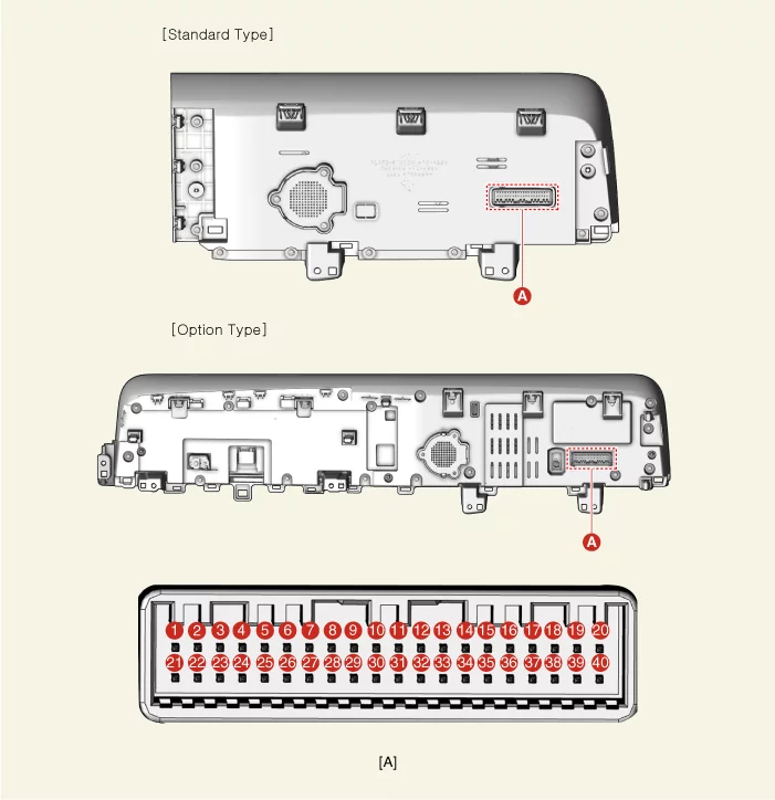
| Terminale | Connettore A | ||
| Funzione | Terminale | Funzione | |
| 1 | Massa | 21 | Ingresso interruttore trip ( - ) |
| 2 | Illuminazione ( - ) | 22 | Ingresso interruttore trip 1 ( + ) |
| 3 | Ingresso interruttore reostato (giù) | 23 | Ingresso interruttore trip 2 ( + ) |
| 4 | Ingresso interruttore reostato (su) | 24 | Ingresso interruttore comando manopola ( + ) |
| 5 | Fermo | 25 | Ingresso interruttore comando manopola ( - ) |
| 6 | AT (posizione 'P') | 26 | - |
| 7 | AT (posizione 'R') | 27 | - |
| 8 | AT (posizione 'N') | 28 | - |
| 9 | AT (posizione 'D') | 29 | M-CAN (Low) |
| 10 | AT (posizione 'S') | 30 | M-CAN (High) |
| 11 | - | 31 | - |
| 12 | Velocità veicolo (uscita) | 32 | C-CAN (Alta) |
| 13 | Ingresso alternatore | 33 | C-CAN (Low) |
| 14 | Ingresso sensore livello carburante (+) | 34 | - |
| 15 | - | 35 | - |
| 16 | Ingresso sensore livello carburante (-) | 36 | - |
| 17 | - | 37 | Massa |
| 18 | Spia di avvertimento airbag | 38 | - |
| 19 | Ingresso interruttore pressione olio | 39 | IG 1 |
| 20 | - | 40 | Batteria (+) |
Rimozione e installazione del quadro strumenti
Rimozione
[Tipo standard]- Scollegare il morsetto negativo (-) della batteria.
- Rimuovere la finitura centrale del cruscotto. (Vedere Carrozzeria - "Finitura cruscotto")
- Rimuovere la griglia dell'altoparlante centrale anteriore.
- Rimuovere la griglia (A) dell'altoparlante centrale anteriore utilizzando l'attrezzo di rimozione.
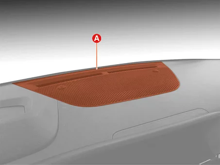
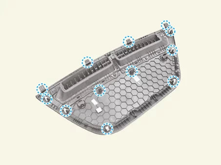
Posizione delle clip:
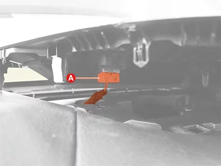
- Scollegare il connettore (A) del sensore luce automatica.
- Rimuovere la griglia (A) dell'altoparlante centrale anteriore utilizzando l'attrezzo di rimozione.
- Rimuovere la copertura (A) del display head-up (HUD) utilizzando l'apposito attrezzo di rimozione.
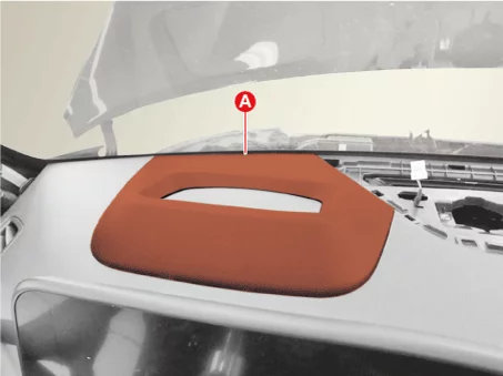

Posizione delle clip: - Rimuovere il quadro strumenti (A) dopo aver rimosso le viti.
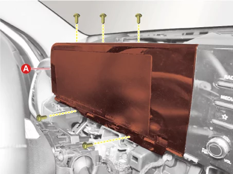
- Scollegare i connettori del quadro strumenti (A).
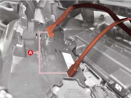
- Scollegare il morsetto negativo (-) della batteria.
- Rimuovere la bocchetta centrale dell'aria. (Fare riferimento a Carrozzeria - "Bocchetta aria plancia")
- Rimuovere la griglia dell'altoparlante centrale anteriore.
- Rimuovere la griglia (A) dell'altoparlante centrale anteriore utilizzando l'attrezzo di rimozione.
Posizione delle clip: - Scollegare il connettore (A) del sensore luce automatica.
- Rimuovere la griglia (A) dell'altoparlante centrale anteriore utilizzando l'attrezzo di rimozione.
- Rimuovere la copertura (A) dell'unità del display head-up (HUD).
Posizione delle clip: - Rimuovere il pannello superiore della plancia centrale (A) utilizzando l'attrezzo di rimozione.
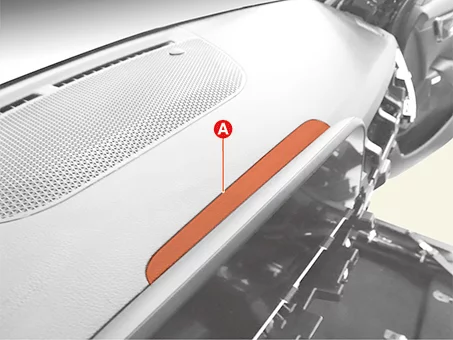
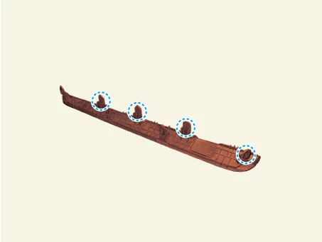
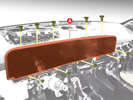
Posizione delle clip: - Rimuovere il quadro strumenti (A) dopo aver rimosso le viti di fissaggio.
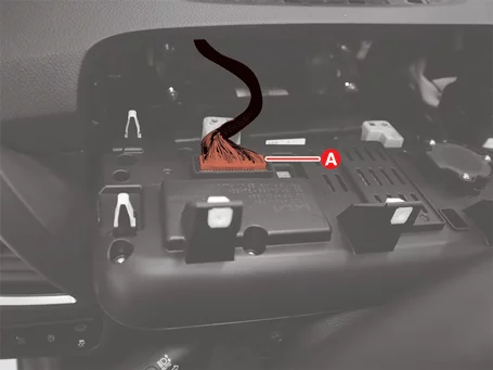
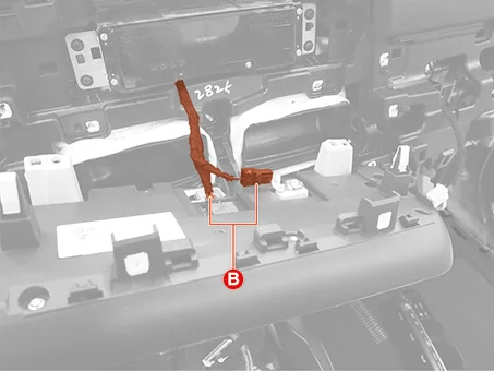
- Scollegare il connettore del quadro strumenti (A), (B).
Installazione
- Installare seguendo la procedura inversa a quella di rimozione.
- Eseguire la procedura seguente con il KDS quando si sostituisce il quadro strumenti. (Gestione S/W → Modulo quadro strumenti → Codifica variante CLU) (Gestione S/W → Modulo quadro strumenti → Impostazione chilometraggio)
Consultare la schermata KDS per le condizioni operative e i dettagli.
Questa pagina ti è stata utile?