Ignition Distributor Repair

Ignition coil check.
1. OHMMETER.
2. TERMINALS C AND TAC.
3. OHMMETER.
4. TERMINAL .
5. OHMMETER
PROCEDURE.
1. Check the ignition coil windings for open circuits and short to "ground"..
"ground"..
Step
1. Set the ohmmeter to the highest range. The measured resistance
should be very high ("infinite"). Otherwise, replace the coil. Step
2. Set the ohmmeter to the most sensitive range. The measured
resistance should be very low (close to zero). Otherwise, replace the
coil..
Step 3. Set the ohmmeter to the highest range. The measured resistance should not be very high, as in step
1. Otherwise, replace the coil.

Pick-up coil check
1. ELECTRONIC MODULE.
2. PICK-UP COIL ASSEMBLY.
3. PICK-UP COIL LEADS DISCONNECTED FROM ELECTRONIC MODULE.
4. OHMMETER.
5. OHMMETER
PROCEDURE.
2. Remove the rotor and disconnect the pick-up coil leads from the electronic module..
3. Connect the ohmmeter sequentially using methods 1 and 2, see figure. Check.
magnetic pick-up sensor coil..
4. Check the coil for an open circuit..
Step
1. The measured resistance must be very high ("infinite"). Otherwise,
replace the coil..
Step
2. The measured resistance must be within 500–1500 ohms. If the resistance value is outside this range, replace
the coil.
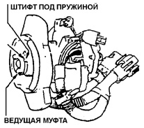
Removal of drive coupling pin
PROCEDURE.
5. Remove the spring. Make alignment marks on the drive coupling and shaft to facilitate
subsequent assembly. Support the coupling on a V-block. Drive out the pin and remove the coupling. Remove all burrs with a file and remove the shaft.
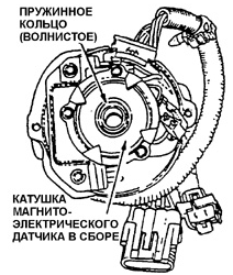
Removal of magnetic pick-up sensor coil
PROCEDURE.
6. To remove the coil, first remove the thin spring ring..
7. Remove the coil by lifting it up.

Removal of electronic module
PROCEDURE.
8. Disconnect the module electrical connector, remove two screws and remove the module. Check the module with test equipment..
9. Wipe the distributor base and module clean and apply silicone grease to the module mounting area to improve heat dissipation from the module..
10. Install and secure the module. Connect the connector..
11. Install the sensor coil and the thin spring ring..
12. Assemble the shaft and coupling, and install the pin..
13. Turn the shaft to check that it rotates freely..
14. If the shaft binds, loosen the sensor coil mounting, eliminate the binding and
tighten the mounting again..
15. Install the rotor and cover.
Test yourself
A quick Daewoo Nexia quiz: every answer comes with an explanation and a link to the manual page.