Removal and Installation - Rear Axle Shaft
Special Service Tools / General Equipment
 |
100-001 (T50T-100-A) Slide hammer |
 |
205-832 Axle Shaft Puller TKIT-2006C-FFMFLM TKIT-2006C-LM TKIT-2006C-RH |
Removal
NOTICE: Never lift or support the axle shaft by the inboard or outboard constant velocity (CV) joint only. Damage to the CV joint will occur.
NOTICE: Never use a hammer to remove or install the axle shafts. Damage to the CV joint may occur.
NOTICE: Never use the axle shaft assembly as a lever to pry other components. Damage to the axle shaft or CV joint may occur.
NOTICE: Keep the boots away from sharp edges and hot exhaust system components. Damage to the axle shaft boots will occur.
NOTICE: Do not drop the assembled axle shafts. An impact may cut the boots from the inside without visible external damage.
- Remove the wheel speed sensor.
REFER TO: Rear Wheel Speed Sensor - AWD (206-09 Anti-Lock Brake System (ABS) and Stability Control System, Removal and Installation). - Remove the wheel bearing and hub assembly.
REFER TO: Wheel Bearing and Hub Assembly - AWD (204-02 Rear Suspension, Removal and Installation). - Using the special tools, remove the rear axle shaft.
Use the special service tools: 205-832 Axle Shaft Puller, 100-001 (T50T-100-A) Slide Hammer.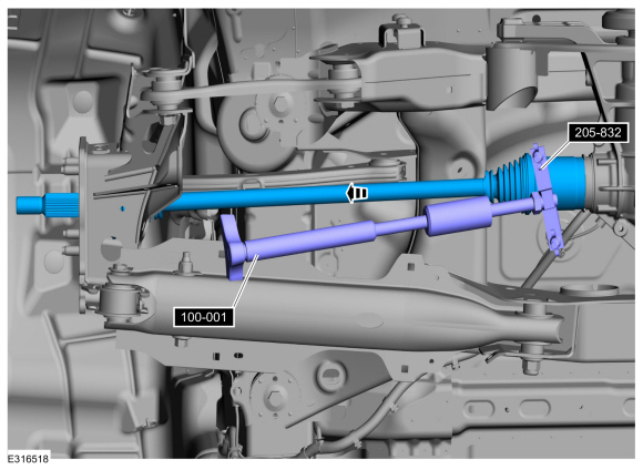
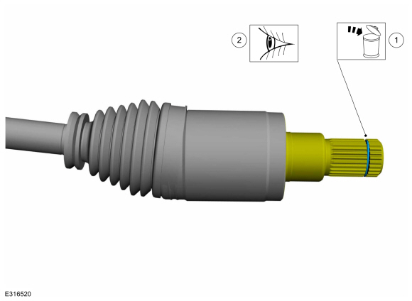
- Remove and discard the axle shaft retaining ring.
- Inspect the end of the axle shaft for damage.
Installation
- If necessary,
Replace the rear axle shaft seal.
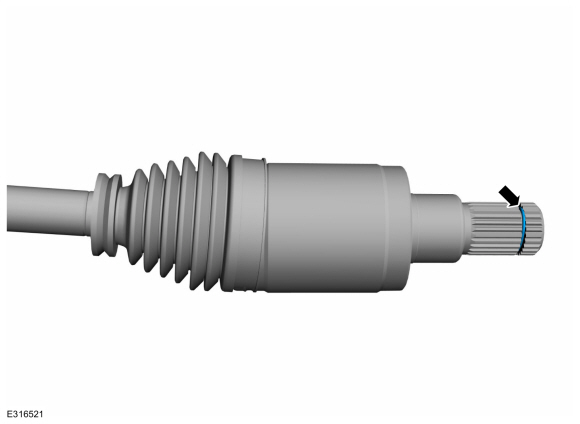
REFER TO: Rear Axle Shaft Seal (205-02 Rear Axle/Differential, Removal and Installation). - Install a new rear axle shaft retaining ring.
NOTICE: Complete the output state control within 5 minutes of activation. Failure to complete the output state control within 5 minutes may result in damage to the RDU clutch motor.
Left side only.- Using the diagnostic scan tool, activate the following AWD actuators. PID: RDU_TRQ_REQ# to approximately 500 N·m.
- Install the rear axle shaft.
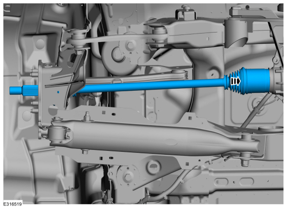
- Left side only.
- Exit output state control.
- Check and add differential fluid.
REFER TO: Differential Fluid Level Check (205-02 Rear Axle/Differential, General Procedures). - Install the wheel bearing and hub assembly.
REFER TO: Wheel Bearing and Hub Assembly - AWD (204-02 Rear Suspension, Removal and Installation). - Install the wheel speed sensor.
REFER TO: Rear Wheel Speed Sensor - AWD (206-09 Anti-Lock Brake System (ABS) and Stability Control System, Removal and Installation).
Test yourself
A quick Ford Escape quiz: every answer comes with an explanation and a link to the manual page.