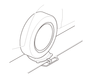
Raise the vehicle on a lift, and make sure it is securely supported.
Front Wheel
1.
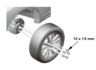
Remove the front wheel.
Lower Ball Joint Lower Arm Side - Disconnection
i225
1.
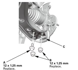
Remove the flange bolt (A).
2.
Remove the flange nuts (B).
3.
Disconnect the lower ball joint (C) from the lower arm.
Front Lower Arm
12x125mm
1.
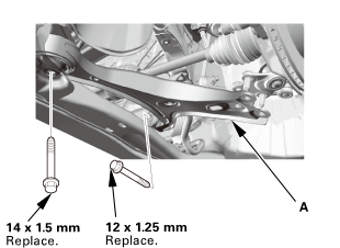
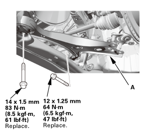
Remove the lower arm (A).
Front Lower Arm
Except 18 inch wheel
mm:2mm
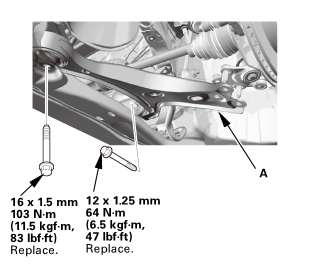
18 inch wheel
1.5mmi2mm(s.si:in-fl)
1.
Install the lower arm (A).
Lower Ball Joint Lower Arm Side - Reconnection
55(ini15mm(skg!m,12x125mm
1.
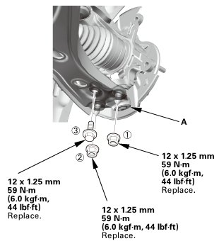
Connect the lower ball joint (A) to the lower arm.
2.
Install the new flange nuts and the new flange bolt in the sequence shown.
Front Wheel
mmmln-mnomm
1.
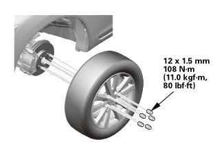
Install the front wheel.
NOTE: Before installing the wheel, clean the mating surfaces between the brake disc and the inside of the wheel.
Pre-Alignment Checks
For proper inspection and adjustment of the wheel alignment, do these checks:
1.
Release the parking brake to avoid an incorrect measurement.
2.
Make sure the suspension is not modified.
3.
Make sure the fuel tank is full, and that the tire repair kit, the spare tire, the jack, and the tools are in place on the vehicle.
4.
Check the tire size and tire pressure according to tire information.
Caster - Inspection
Use commercially available computerized four wheel alignment equipment to measure wheel alignment (caster, camber, toe, and turning angle). Follow the equipment manufacturer's instructions.
1.
Check the caster angle.
USA and Canada models
Caster angle:
Except Si:
5 ° 19 ’±30 ’
Si (Without 18 inch wheel):
5 ° 22 ’±30 ’
Si (With 18 inch wheel):
5 ° 15 ’±30 ’
Mexico models
Caster angle:
Without 18 inch wheel:
5 ° 10 ’±30 ’
With 18 inch wheel:
5 ° 6 ’±30 ’
If the measurement is within specifications, measure the front camber angle.
If the measurement is not within specifications, check for bent or damaged suspension components.
Camber - Inspection
Use commercially available computerized four wheel alignment equipment to measure wheel alignment (caster, camber, toe, and turning angle). Follow the equipment manufacturer's instructions.
1.
Check the camber angle.
USA and Canada models
Camber angle:
Except Si:
Front:
0 ° 00 ’±30 ’
Rear:
-0 ° 45 ’±45 ’
Si (Without 18 inch wheel):
Front:
-0 ° 04 ’±30 ’
Rear:
-0 ° 52 ’±45 ’
Si (With 18 inch wheel):
Front:
-0 ° 18 ’±30 ’
Rear:
-0 ° 45 ’±45 ’
(Maximum difference between the front right and left side: 0 ° 45 ’)
Mexico models
Camber angle:
Front:
0 ° 20 ’±30 ’
Rear:
-0 ° 22 ’±45 ’
(Maximum difference between the front right and left side: 0 ° 45 ’)
If the measurement is within specification, measure the toe-in.
If the measurement for the front camber is not within the specification, go to front camber adjustment.
If the measurement for the rear camber is not within the specification, check for bent or damaged suspension components.
Front Toe - Inspection
Use commercially available computerized four wheel alignment equipment to measure wheel alignment (caster, camber, toe, and turning angle). Follow the equipment manufacturer's instructions.
1.
Set the steering column to the middle tilt position and telescopic positions.
2.
Center the steering wheel spokes, and install a steering wheel holder tool.
3.
Check the toe with the wheels pointed straight ahead.
Front toe-in: 0±2 mm (0±0.08 in)
If adjustment is required, go to the front toe adjustment.
If no adjustment is required, remove the alignment equipment.
Turning Angle - Inspection
Use commercially available computerized four wheel alignment equipment to measure wheel alignment (caster, camber, toe, and turning angle). Follow the equipment manufacturer's instructions.
Except '12 models
1.
Turn the wheel right and left while applying the brake, and measure the turning angle of both wheels.
USA and Canada models
Turning angle:
Except Si:
Inward:
38 ° 30 ’±2 °
Outward (reference):
30 ° 47 ’±1 °
Si (Without 18 inch wheel):
Inward:
38 ° 22 ’±2 °
Outward (reference):
30 ° 41 ’±1 °
Si (With 18 inch wheel):
Inward:
36 ° 33 ’±2 °
Outward (reference):
29 ° 53 ’±1 °
Mexico models
Turning angle:
Without 18 inch wheel:
Inward:
39 ° 12 ’±2 °
Outward (reference):
31 ° 14 ’±1 °
With 18 inch wheel:
Inward:
36 ° 58 ’±2 °
Outward (reference):
30 ° 16 ’±1 °
2.
If the measurement is not within the specifications, even up both sides of the tie-rod threaded section length while adjusting the front toe.
3.
If it is correct, but the turning angle is not within the specifications, check for bent or damaged suspension components.
'12 models
1.
Turn the wheel right and left while applying the brake, and measure the turning angle of both wheels.
USA and Canada models
Turning angle:
Except Si:
Inward:
38 ° 43 ’±2 °
Outward (reference):
30 ° 55 ’±1 °
Si:
Inward:
38 ° 36 ’±2 °
Outward (reference):
30 ° 49 ’±1 °
Mexico models
Turning angle:
Inward:
39 ° 15 ’±2 °
Outward (reference):
31 ° 21 ’±1 °
2.
If the measurement is not within the specifications, even up both sides of the tie-rod threaded section length while adjusting the front toe.
3.
If it is correct, but the turning angle is not within the specifications, check for bent or damaged suspension components.
?
Test yourself
A quick Honda Civic quiz: every answer comes with an explanation and a link to the manual page.

 i225
 12x125mm

 mm:2mm
 1.5mmi2mm(s.si:in-fl)
 55(ini15mm(skg!m,12x125mm
 mmmln-mnomm