Standard Diagnostic Troubleshooting FlowNotes on Diagnosis. The phenomena listed in the following table are not abnormal.
Condition
Description
System Check Sound
When the engine is started, a dull knocking sound may sometimes be heard from the engine compartment. This is because the system performs a self-check.
ABS Operation Sound
A motor sound (whining) can be heard inside the ABS hydraulic unit.
A grinding sound is generated together with brake pedal vibration.
During ABS operation, sound may come from the vehicle chassis due to repeated depressing and releasing of the brake. (Knocking: suspension; squeal: tires)
ABS Operation (Longer Stopping Distance)
On road surfaces such as snowy or gravel roads, the stopping distance of vehicles with ABS may sometimes be longer than that of other vehicles. Accordingly, advise the customer to drive safely on such roads by reducing vehicle speed.
Detection conditions may vary depending on the DTC. When checking the symptom after the DTC has been erased, make sure the requirements listed in the "Comments" are met.
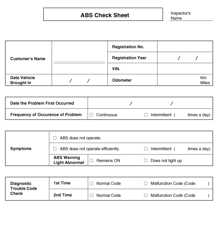
ABS ChecklistSymptom Table
Symptom
Suspect area
ABS does not operate.
Only if items 1~4 are all normal and the problem still occurs, replace the HECU.
Check the DTC to confirm that a normal code is output.
Power supply circuit.
Speed sensor circuit.
Check the hydraulic circuit for leaks.
ABS does not operate intermittently.
Only if items 1~4 are all normal and the problem still occurs, replace the ABS hydraulic unit.
Check the DTC to confirm that a normal code is output.
Wheel speed sensor circuit.
Stop lamp switch circuit.
Check the hydraulic circuit for leaks.
Communication with GDS is not possible. (Communication with any system is not possible)
Power supply circuit
CAN line
Communication with GDS is not possible. (Communication with ABS only is not possible)
Power supply circuit
CAN line
HECU
When the ignition switch is ON (engine off), the ABS warning lamp does not illuminate.
ABS warning lamp circuit
HECU
Even after starting the engine, the ABS warning lamp remains illuminated.
ABS warning lamp circuit
HECU
Detection Condition
Symptom Condition
Possible Cause
Brake operation depends on driving conditions and road surface conditions, so diagnosis may be difficult. However, if a normal DTC is displayed, check the following possible causes. If the problem still occurs, replace the ABS control module.
Faulty power supply circuit
Faulty wheel speed sensor circuit
Faulty hydraulic circuit due to leakage
Faulty HECU
Inspection Procedures. Check DTC.
Connect the GDS to the Data Link Connector (DLC) and turn the ignition ON.
Make sure that a DTC is output.
Is a DTC output?
YES: Check the power supply circuit.
YES: Erase the DTC and repeat the check using the GDS.
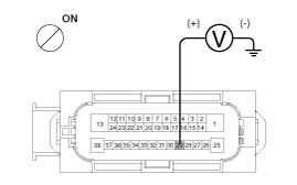
Disconnect the connector from the ABS control module.
Turn the ignition ON. Measure the voltage between terminal 29 of the ABS control module harness-side connector and body ground.
Specification: Approximately B+
Is the voltage within specification?
NO: Check the ground circuit.
NO: Check the harness or connector between the fuse (10A) in the engine compartment junction block and the ABS control module. Repair if necessary.
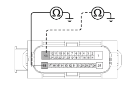
Disconnect the connector from the ABS control module.
Check the continuity between terminals 13 and 38 of the ABS control module harness-side connector and a ground point.
Is there continuity?
NO: Check the wheel speed sensor circuit.
YES: Repair the open in the wire and ground point.
Refer to DTC troubleshooting procedures.
Is this normal?
NO > Check the hydraulic circuit for leaks.
NO > Repair or replace the wheel speed sensor.
Refer to hydraulic lines.
Check the hydraulic lines for leaks.
Is this normal?
NO > If the problem persists, replace the ABS control module.
NO > Repair the hydraulic lines for leaks.
Check the power supply circuit. Check the ground circuit. Check the wheel speed sensor circuit. Check the hydraulic circuit for leaks. Detection Condition
Symptom Condition
Possible Cause
Brake operation depends on driving conditions and road surface conditions, so diagnosis may be difficult. However, if a normal DTC is displayed, check the following possible causes. If the problem still occurs, replace the ABS control module.
Faulty power supply circuit
Faulty wheel speed sensor circuit
Faulty hydraulic circuit due to leakage
Faulty HECU
Inspection Procedures. Check DTC.
Connect the GDS to the Data Link Connector (DLC) and turn the ignition ON.
Make sure that a DTC is output.
Is a DTC output?
NO: Check the wheel speed sensor circuit.
YES: Erase the DTC and repeat the check using the GDS.
Refer to DTC troubleshooting procedures.
Is this normal?
NO > Check the stop lamp switch circuit.
NO > Repair or replace the wheel speed sensor.
Verify that the stop lamp illuminates when the brake pedal is depressed and goes off when the brake pedal is released.
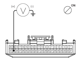
Measure the voltage between terminal 23 of the ABS control module harness side connector and body ground with the brake pedal depressed.
Specification: Approximately B+
Is the voltage within specification?
NO > Check the hydraulic circuit for leaks.
NO > Repair the stop lamp switch. Repair the open circuit in the wire between the ABS control module and the stop lamp switch.
Refer to hydraulic lines.
Check the hydraulic lines for leaks.
Is this normal?
NO > If the problem persists, replace the ABS control module.
NO > Repair the hydraulic lines for leaks.
Check the wheel speed sensor circuit. Check the stop lamp switch circuit. Check the hydraulic circuit for leaks. Detection Condition
Symptom Condition
Possible Cause
A malfunction may exist in the power supply (including ground) circuit of the diagnostic line.
Open in the wire
Poor ground
Faulty power supply circuit
Inspection Procedures. Check the power supply circuit for diagnosis.
Measure the voltage between terminal 16 of the data link connector and body ground.
Specification: Approximately B+
Is the voltage within specification?
NO > Check the ground circuit for diagnosis.
NO > Repair the open circuit in the wire. Check and replace the fuse in the engine compartment junction block.
Check the continuity of the circuit between terminal 4 of the data link connector and body ground.
Is there continuity?
NO > Repair the open circuit in the wire between terminal 4 of the data link connector and the ground point.
Check the ground circuit for diagnosis. Detection Condition
Symptom Condition
Possible Cause
If communication with GDS is not possible, the cause may be an open in the HECU power supply circuit or an open in the diagnostic output circuit.
Open in the wire
Faulty HECU
Faulty power supply circuit
Inspection Procedures. Check the CAN line integrity.
Disconnect the connector from the ABS control module.
Check the continuity of the circuit between terminals 26, 14 of the ABS control module connector and terminals 3, 11 of the data link connector.
Is there continuity?
NO > Check the power supply to the ABS control module.
NO > Repair the open circuit in the wire.
Disconnect the connector from the ABS control module.
Turn the ignition ON. Measure the voltage between terminal 29 of the ABS control module harness-side connector and body ground.
Specification: Approximately B+
Is the voltage within specification?
NO > Check for poor ground.
NO > Check the harness or connector between the fuse (10A) in the engine compartment junction block and the ABS control module. Repair if necessary.
Check the continuity of the circuit between terminal 4 of the data link connector and the ground point.
NO > Replace the ABS control module and repeat the check.
NO > Repair the open circuit in the wire or poor ground.
Check the power supply to the ABS control module. Check for poor grounding. Detection Condition
Symptom Condition
Possible Cause
When current flows through the HECU, the ABS warning lamp turns off. Turn the ignition switch to OFF for the initial check. Therefore, if the lamp does not illuminate, the cause may be an open in the lamp power supply circuit, a burned-out bulb, an open in both circuits between the ABS warning lamp and the HECU, or a faulty HECU.
Faulty ABS warning lamp bulb
A blown fuse related to ABS in the engine compartment junction block.
Faulty ABS warning lamp module
Faulty HECU
Inspection Procedures. Check the problem.
Disconnect the connector from the ABS control module and turn the ignition switch ON.
Does the ABS warning lamp illuminate?
NO > Check again after replacing the ABS HECU.
NO > Check the power supply to the ABS warning lamp.
Disconnect the instrument cluster connector (M08) and turn the ignition switch ON.
Measure the voltage between terminal (M08) 39 of the instrument cluster harness side connector and body ground.
Specification: Approximately B+
Is the voltage within specification?
NO > Check the CAN circuit resistance of the ABS warning lamp.
NO > Check whether the fuse is blown.
Disconnect the instrument cluster connector (M08) and turn the ignition switch OFF.
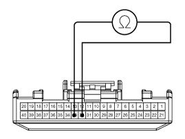
Measure the resistance between terminals (M08) 32 and 33 of the instrument cluster harness side connector.
Specification: 60 Ω
Is the resistance within specification?
NO > Repair the ABS warning lamp or replace the instrument cluster assembly.
NO > Check the CAN circuit wiring for the ABS warning lamp.
Disconnect the instrument cluster connector (M08) and the ABS HECU connector, then turn the ignition switch OFF.
Check the continuity between terminal (M08) 32 of the instrument cluster harness side connector and terminal 26 of the ABS HECU harness side connector. Check the continuity between terminal (M08) 33 of the instrument cluster harness side connector and terminal 14 of the ABS HECU harness side connector.
Specification: Below 1 Ω
Is the resistance within specification?
NO > Repair the short circuit in the wiring between terminals 26, 14 of the ABS HECU harness connector and the ABS warning lamp module.
NO > Repair the open circuit in the wiring between terminals 26, 14 of the ABS HECU harness connector and the ABS warning lamp module.
Check the power supply to the ABS warning lamp. Check the resistance of the ABS warning lamp CAN circuit. Check the wiring of the ABS warning lamp CAN circuit. Detection Condition
Symptom Condition
Possible Cause
If the HECU detects a malfunction, it turns on the ABS warning lamp and simultaneously disables ABS control. At this time, the HECU stores the DTC in memory. Even though a normal code is output, if the ABS warning lamp remains on, the cause may be an open or short circuit in the ABS warning lamp circuit.
Open in the wire
Faulty instrument cluster assembly
Faulty ABS warning lamp module
Faulty HECU
Inspection Procedures. Check the DTC output.
?
Test yourself
A quick Hyundai Elantra AD quiz: every answer comes with an explanation and a link to the manual page.