Braking System
Circuit Diagrams
In this manual: Braking System
~1min read
SCHEMATIC DIAGRAM
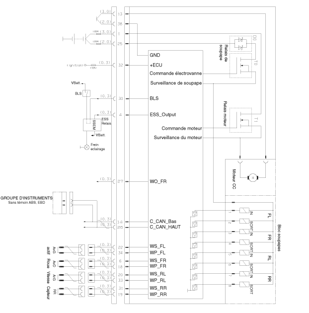
TERMINAL FUNCTION

| Connector Terminal | Specification | ||
| NO | Description | MAX | MIN. |
| 13 | Pump Motor Ground | 39A | 10A |
| 38 | Ground for Solenoid Valves and ECU | 15A | 2A |
| 1 | Power Supply for Pump Motor | 39A | 10A |
| 25 | Power Supply for Solenoid Valves | 15A | 2A |
| 32 | ECU Power Supply Voltage | 1a | 500 mA |
| 22 | Front Left Wheel Speed Sensor AvG Signal | 16.8 mA | 5.9 mA |
| 6 | Front Right Wheel Speed Sensor AvD Signal | ||
| 20 | Rear Left Wheel Speed Sensor ArG Signal | ||
| 31 | Rear Right Wheel Speed Sensor ArD Signal | ||
| 34 | Wheel Speed Sensor Common Ground | 16.8 mA | 5.9 mA |
| 18 | Front Wheel Speed Sensor Power Supply | ||
| 33 | Rear Left Wheel Speed Sensor ArG Power Supply | ||
| 19 | Rear Right Wheel Speed Sensor ArD Power Supply | ||
| 27 | Wheel Speed Output Signal | Drain Port | - |
| 4 | Emergency Stop Output Signal | 200 mA | 100 mA |
| 41 | CAN Low | 30 mA | 20 mA |
| 26 | CAN High | ||
| 30 | Brake Light Switch Signal | 10 mA | 5 mA |
Test yourself
A quick Hyundai i20 quiz: every answer comes with an explanation and a link to the manual page.
Was this page helpful?