Braking System
Description and Operation
In this manual: Braking System
6steps
~36min
2/5difficulty
Done 0 of 6
Description
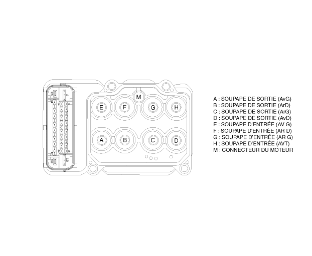
These specifications apply to the HCU (Hydraulic Control Unit) and ECU (Electronic Control Unit) of the HECU (Hydraulic and Electronic Control Unit). These specifications apply to the wiring design and installation of the ABS/ESP/ECU. This unit has the following functions.- Input signals from the pressure sensor, steering wheel angle sensor, lateral acceleration and yaw rate sensor, and wheel speed sensors attached to each wheel.
- Brake force / driving force / yaw moment control
- Fail-Safe Function
- Self-check function
- Interface with external diagnostic tool
- The maximum length of the brake line between the master cylinder and the HECU inlet must be 1 meter.
- The position must not be close to the engine block and not lower than the wheel.
- Overvoltage: When an increased voltage is detected (above 17 ± 0.5 V), the ECU switches off the valve relay and interrupts system operation. When the voltage returns to the operating range, the system returns to normal after the initialization phase.
- Undervoltage: When a reduced voltage is detected (below 9.5 ± 0.5 V), ABS control is disabled and the warning lamp illuminates. When the voltage returns to the operating range, the warning lamp goes off and the ECU returns to normal operation.
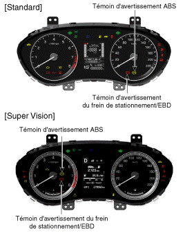
- ABS WARNING LAMP MODULE: The ABS warning lamp indicates the self-check and the ABS fault status. The ABS warning lamp illuminates:
- During the initialization phase after ALL ON (continuously for 3 seconds).
- When ABS functions related to a fault are deactivated.
- In diagnostic mode.
- When the ECU connector is disconnected from the ECU.
- The instrument cluster warning lamp illuminates when communication with the CAN module is not possible.
- EBD / PARK WARNING LAMP MODULE: The EBD warning lamp indicates the self-check and the EBD fault status. However, if the parking brake switch is active, the EBD warning lamp illuminates regardless of EBD function status. The EBD warning lamp illuminates:
- During the initialization phase after ALL ON (continuously for 3 seconds).
- When the parking brake switch is on or when the brake fluid level is low.
- When the EBD function is faulty.
- In diagnostic mode.
- When the ECU connector is disconnected from the ECU.
- The instrument cluster warning lamp illuminates when communication with the CAN module is not possible.
ABS CONTROL
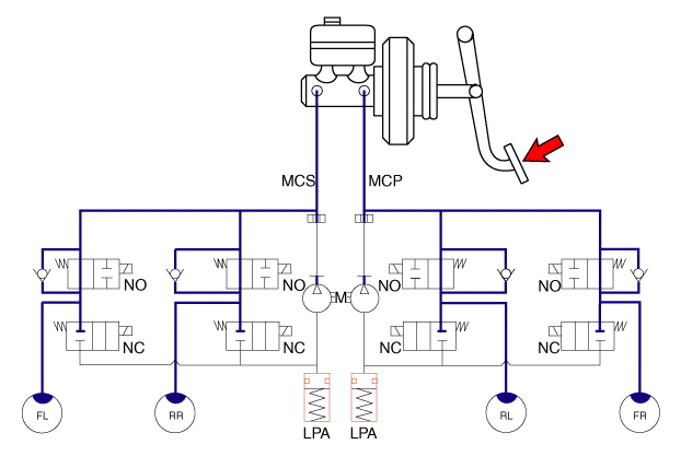
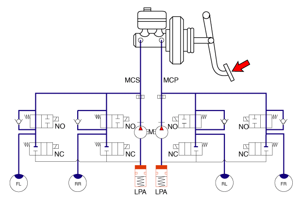
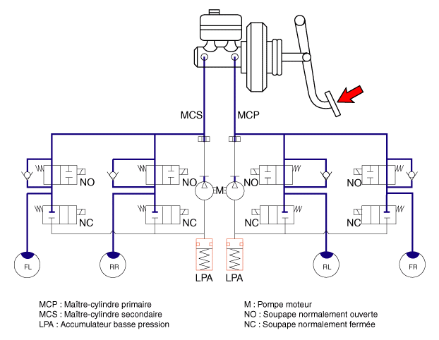
- NORMAL BRAKING WITHOUT ABS: During normal braking, voltage is not applied to the solenoid valve, the inlet valve is open, and the outlet valve is closed. When the brake is applied, brake fluid is supplied to the wheel cylinder through the solenoid valve to activate the brake. When the brake is released, brake fluid returns to the master cylinder through the inlet valve and the regulating valve.
Solenoid valve STATUS Valve Communication PUMP
MotorInlet valve (NO) OFF Open Master cylinder → Wheel cylinder OFF Outlet valve (NC) OFF Closed Wheel cylinder → Reservoir
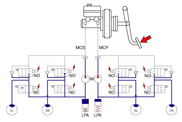
- DUMP MODE: In an emergency braking situation, if the wheels begin to lock, the HECU sends a signal to the solenoid valve to reduce brake fluid pressure. Voltage is then applied to each solenoid. At this point, the inlet valve closes and brake fluid is blocked from the master cylinder. The outlet valve opens, and brake fluid circulates to the reservoir through the wheel cylinder, which causes the pressure to drop.
SOLENOID VALVE STATUS Valve Communication PUMP
MotorInlet valve (NO) WE Closed Master cylinder → Wheel cylinder WE Outlet valve (NC) WE Open Wheel cylinder → Reservoir
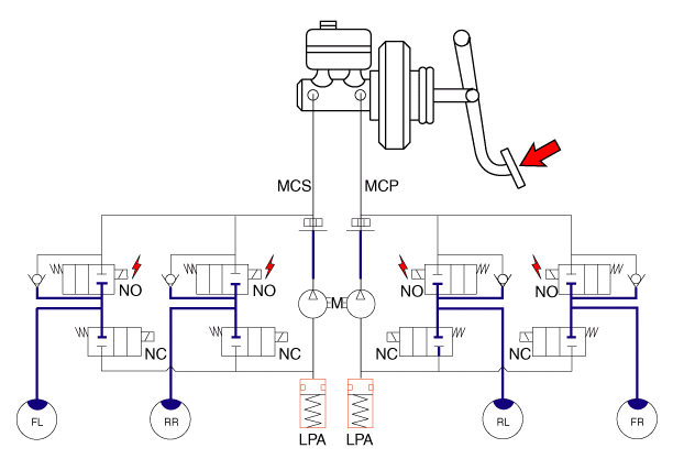
- HOLD MODE: When brake fluid pressure in the wheel cylinder reaches the minimum level, the HECU sends a signal to the solenoid valve so that it maintains the specified pressure and the inlet valve is energized (as opposed to the outlet valve). The inlet and outlet valves are then closed, and brake fluid is held at that level inside the wheel cylinder.
SOLENOID VALVE STATUS Valve Communication PUMP
MotorInlet valve (NO) WE Closed Master cylinder → Wheel cylinder OFF Outlet valve (NC) OFF Closed Wheel cylinder → Reservoir
- INCREASE MODE: If the HECU determines that the wheels are not locked, it cuts the voltage supply to the solenoid valve. Voltage is not supplied to each solenoid valve, and brake fluid flows into the wheel cylinder through the inlet valve, which increases the pressure.
SOLENOID VALVE STATUS Valve Communication PUMP
MotorInlet valve (NO) OFF Open Master cylinder → Wheel cylinder WE Outlet valve (NC) OFF Closed Wheel cylinder → Reservoir
Test yourself
A quick Hyundai i20 quiz: every answer comes with an explanation and a link to the manual page.
Was this page helpful?