Body Electrical System
General Information
In this manual: Body Electrical System
39steps
~234min
4/5difficulty
Done 0 of 39
GENERAL INFORMATION, TROUBLESHOOTING
BEFORE TROUBLESHOOTING- Check the fuses in the fuse/relay box.
- Using the battery tester (MCR-570 KIT), check the battery and state of charge, clean and tighten the connections. (Refer to Engine Electrical System - "Battery.")
- Check the generator belt tension (D).
- Make sure the connectors are clean and the terminal wires are not loose.
- Make sure multi-pin connectors are coated with grease (except waterproof connectors).
- All connectors are equipped with a push-lock system. (B)
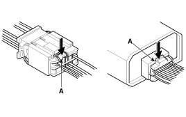
- Some connectors have a clip on the side that allows attachment to a bracket on the housing or another component. This clip has a locking lock.
- Some mounted connectors cannot be disconnected unless you release the lock and remove the connector from the holder (B).
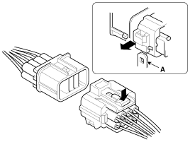
- Never try to disconnect connectors by pulling on the wires. Instead, pull on the connector housing.
- Always reinstall plastic covers.
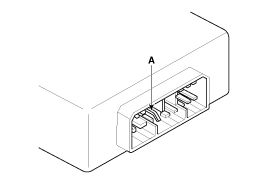
- Before connecting connectors, make sure the terminals (A) are in place and not bent.
- Make sure the plug (A) and rubber seals (B) are not loose.
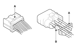
- The rear of some connectors is coated with grease. Add grease as necessary. If the grease (A) is contaminated, replace it.
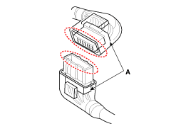
- Insert the connector fully and make sure it is securely locked.
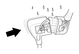
- Route the wires so that the open ends of the covers are facing down.
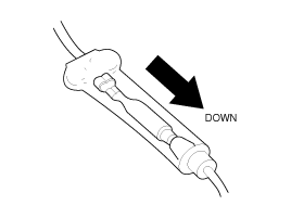
- Secure the cables and harnesses to the frame with clips at the specified locations.
- Carefully remove the clips; do not damage their locks (B).
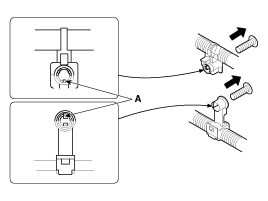
- Insert the clip (A) under the clip base and through the hole at an angle, then compress the expansion tabs to release the clip.
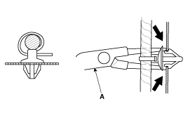
- After installing harness clips, make sure the harness does not contact any moving part.
- Keep harnesses away from exhaust pipes and other hot parts, sharp edges of brackets and holes, screws, and bolts.
- Position the rings correctly in their grooves (A). Do not twist the rings (B).
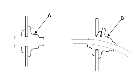
- Do not use cables or harnesses with damaged insulation. Replace or repair cables by wrapping the cut with insulating tape.
- After installing the parts, make sure that the wires are not pinched.
- When using electrical test equipment, follow the manufacturer's instructions and the instructions described in this manual.
- If possible, insert the disassembly tool from the side of the electrical wire (except for waterproof connectors).
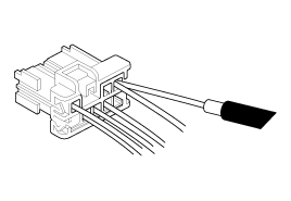
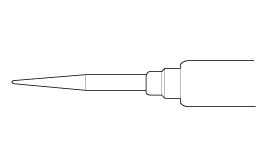
- Use a pointed probe. Refer to the user's manual included in the wiring repair kit. (Publication No.: TRK 015.)
- Verify the complaint. Operate all components of the malfunctioning circuit to check the customer's complaint. Note the symptoms. Do not begin disassembly or testing until the area where the problem occurs has been localized.
- Analyze the circuit diagram. Using the diagram, locate the malfunctioning circuit. Determine how the circuit should operate by tracing the current path from the power source, through the circuit components, to ground. If several circuits malfunction at the same time, the probable causes are weather, a fuse, or a ground. Based on the symptoms and your understanding of how the circuit works, identify one or more possible causes of the problem.
- Isolate the problem by inspecting the circuit. Perform circuit tests to confirm the diagnosis made in step 2. Keep in mind that a logical and simple procedure is the key to effective troubleshooting. First check the most likely causes of the failure. Try to test at easily accessible locations.
- Repair the problem. Once the specific problem has been identified, proceed with the repair. Be sure to use proper tools and safe procedures.
- Confirm the circuit operates properly. Operate all components of the repaired circuit in all modes to make sure the problem has been fully identified. If the problem was a blown fuse, check all circuits dependent on that fuse. Make sure no new problems occur and the original problem does not recur.
| System | Reset |
| Power window Vehicle |
Once the battery is disconnected, discharged, or the related fuse is replaced or reconnected, reset the automatic window system according to the procedure below.
|
| Sunroof | When opening/closing the sunroof, if battery power is not supplied or the battery is discharged, when a fuse is replaced, or when the sunroof is operated using the emergency handle, the sunroof must be initialized as follows.
|
Audio System, Trip Computer and Clock Reset: When reconnecting the battery cable after disconnection, when recharging a discharged battery, or when installing the memory fuse located on the driver's side panel after its removal, it is important to reset the systems listed in the table below. Also, when replacing or reinstalling their fuses after removal, reset them according to the table below. Please refer to the table below when servicing.
| System | Reset |
| TRIP COMPUTER | If the battery is disconnected and reconnected, the functions set on the trip computer are initialized. Therefore, you must provide this information to the customer. |
| CLOCK | When the battery terminals or related fuses are disconnected, the time must be reset on the head unit. (Refer to the audio system owner's manual.) |
| Audio | If the battery is disconnected and reconnected, the customer's radio presets are initialized. Therefore, record the customer's radio presets before service. After service, reset the customer's radio presets in the audio system. |
Test yourself
A quick Hyundai i20 quiz: every answer comes with an explanation and a link to the manual page.
Was this page helpful?