Body Electrical System
Smart Key Unit Components and Component Locations
In this manual: Body Electrical System
~1min read
Components (1)
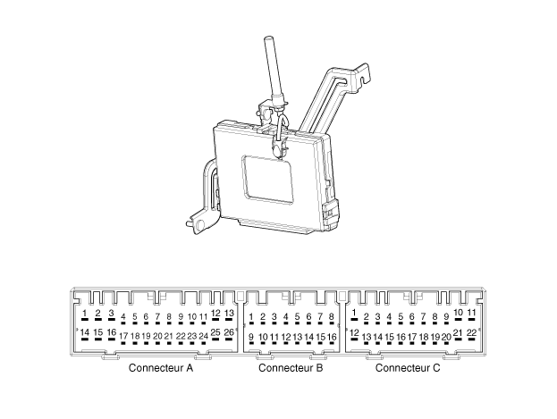
| NO | CONNECTOR A | CONNECTOR B | C-CONNECTOR |
| 1 | CHARGE_BAT V | C_CAN - LOW | SSB Illumination Ground |
| 2 | ESCL Ground | C_CAN - HIGH | Immobilizer Indicator |
| 3 | Ground 1 | - | - |
| 4 | ALL1 | Stop Lamp Fuse | Internal Antenna No. 2 Power Supply |
| 5 | IGN1 Relay | With Brake Switch | Internal Antenna No. 1 Power Supply |
| 6 | SOUND | Immobilizer Data | - |
| 7 | ALL2 | ESCL Activation | - |
| 8 | SSB Switch 2 | Wheel Speed | - |
| 9 | - | Driver Switch | Bumper Antenna Illuminator |
| 10 | - | ESCL Unlock | Passenger Side Antenna |
| 11 | ESCL_COM | Exterior Buzzer | Driver Side Antenna Power Supply |
| 12 | B_CAN_HIGH | P/Clutch Position Switch | SSB ALL Indicator |
| 13 | B-CAN Low | Departure Feedback | SSB Illumination Power |
| 14 | CPU V_BAT | Immobilizer Clock | - |
| 15 | ESCL Battery | - | Room Antenna No. 2 Ground |
| 16 | Ground 2 | SSB ACC LED | Internal Antenna No. 1 Ground |
| 17 | Starter Relay | - | |
| 18 | ALL2 Relay | - | |
| 19 | ACC Relay | - | |
| 20 | - | Bumper Antenna Ground | |
| 21 | - | Passenger Side Antenna Ground | |
| 22 | - | Driver Side Antenna Ground | |
| 23 | RPM | ||
| 24 | COM EMS | ||
| 25 | SSB Switch 1 | ||
| 26 | Passenger Switch |
Test yourself
A quick Hyundai i20 quiz: every answer comes with an explanation and a link to the manual page.
Was this page helpful?