Emission Control System
Circuit Diagrams
In this manual: Emission Control System
~1min read
Schematic Diagram
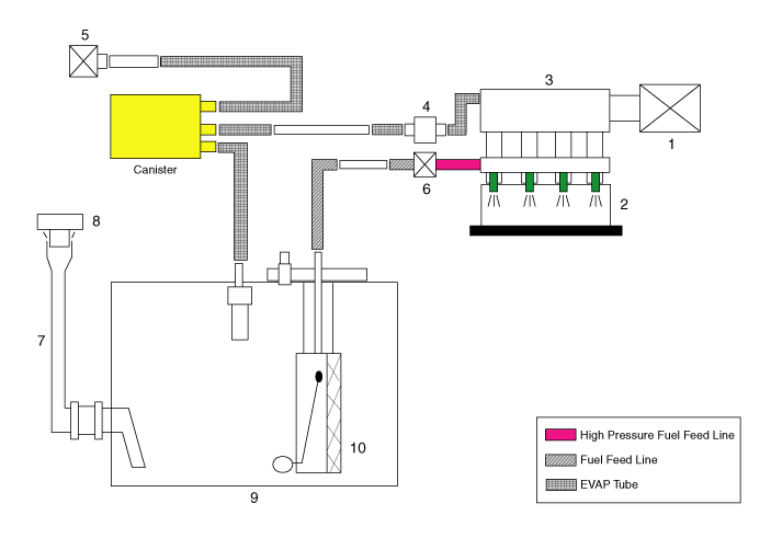
| 1. Air cleaner 2. Pressure pipe and injector 3. Engine 4. Purge control solenoid valve (PCSV) 5. Fuel tank air filter |
6. High-pressure fuel pump 7. Fuel hose 8. Fuel tank cap 9. Fuel tank 10. Low-pressure fuel pump |
Canister: The canister is filled with activated charcoal and absorbs fuel vapor evaporating in the fuel tank. The fuel vapor collected in the canister is drawn into the intake manifold by the ECM/PCM when the applicable conditions are met. Purge Control Solenoid Valve (PCSV): The PCSV is installed in the passage connecting the canister and the intake manifold. It is a duty-cycle solenoid valve controlled by a signal from the ECM/PCM. To draw the absorbed vapor into the intake manifold, the ECM/PCM opens the PCSV; otherwise, the passage remains closed. Fuel Tank Cap: The ratchet tightening device on the threaded fuel tank cap reduces the possibility of incorrect installation that would fail to seal the filler neck. When the gaskets on the fuel tank cap and filler neck flange contact each other, the ratchet produces a clicking sound, indicating that the seal is installed.
Test yourself
A quick Hyundai Palisade quiz: every answer comes with an explanation and a link to the manual page.
Was this page helpful?