DFI System Wiring Diagram
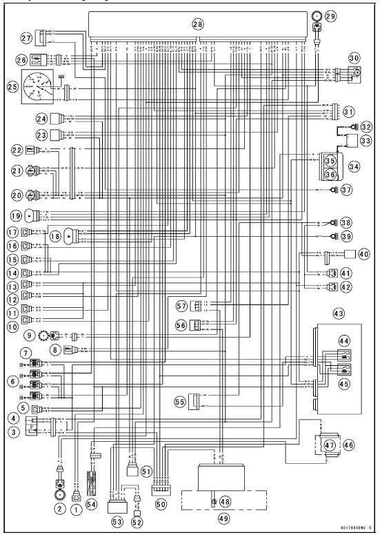
Part Names
1. Air Intake Solenoid Valve (Other than US, CA and CAL Models)
2. Front Wheel Rotation Sensor
3. Engine Stop Switch
4. Starter Button
5. Air Switching Valve
6. Stick Coil #1, #2, #3, #4
7. Spark Plugs
8. Intake Air Temperature Sensor
9. Crankshaft Sensor
10. Secondary Fuel Injector #1
11. Secondary Fuel Injector #2
12. Secondary Fuel Injector #3
13. Secondary Fuel Injector #4
14. Primary Fuel Injector #1
15. Primary Fuel Injector #2
16. Primary Fuel Injector #3
17. Primary Fuel Injector #4
18. Idle Speed Control Valve Actuator
19. Subthrottle Valve Actuator
20. Main Throttle Sensor
21. Subthrottle Sensor
22. Water Temperature Sensor
23. Intake Air Pressure Sensor #2
24. Intake Air Pressure Sensor #1
25. Gear Position Switch
26. Oxygen Sensor (Equipped Models)
27. Joint Connector E
28. ECU
29. Rear Wheel Rotation Sensor
30. Exhaust Butterfly Valve Actuator
31. Immobilizer (Equipped Models)/Kawasaki Diagnostic System Connector
32. Engine Ground
33. Battery
34. Starter Relay
35. Main Fuse 30 A
36. ECU Fuse 15 A
37. Frame Ground 2
38. Frame Ground 3
39. Frame Ground 1
40. Fuel Pump
41. Resister R
42. Resister F
43. Relay Box
44. Fuel Pump Relay
45. ECU Main Relay
46. Fuse Box 1
47. Ignition Fuse 15 A
48. Oil Pressure/Water Temperature/FI/Immobilizer Warning Indicator Light
49. Meter Unit
50. Joint Connector F
51. Vehicle-down Sensor
52. Immobilizer Antenna (Equipped Models)
53. Immobilizer Amplifier (Equipped Models)
54. Ignition Switch
55. Joint Connector A
56. Joint Connector C
57. Joint Connector D
Test yourself
A quick Kawasaki Ninja ZX-10R quiz: every answer comes with an explanation and a link to the manual page.