Fuel System (DFI)
CAN Communication Line
In this manual: Fuel System (DFI)
~1min read
CAN Communication Line Resistance Inspection
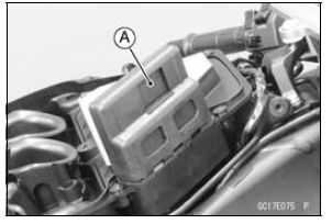
In this model, resistors for CAN communication line are built in the ECU [A] and meter unit.
- Refer to the Meter Unit Inspection in the Electrical System chapter for the resistor in the meter unit.
- Turn the ignition switch to OFF.
- Remove: ECU (see ECU Removal)
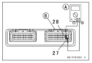
- Connect a digital meter [A] to the ECU connector (black) [B].
- Measure the resistance of the CAN communication line resistor.
CAN Communication Line Resistance (at ECU Connector)
Connections: Terminal 27 ←→ Terminal 28
Standard: 123  125 Ω
If the reading is out of the range, replace the ECU (see ECU Removal/Installation).
If the reading is within the range, resistor of the ECU for CAN communication line is normal.
- Check the wiring for continuity of the CAN communication line (see wiring diagram in this section).
Special Tool - Hand Tester: 57001-1394
If the wiring is open, repair or replace the main harness.
CAN Communication Line Circuit
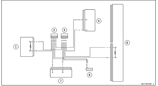
1. Meter Unit
2. Joint Connector C
3. Joint Connector D
4. ESD (Electronic Steering Damper) ECU (ZX1000JD/KD)
5. ECU
6. Immobilizer (Equipped Models)/Kawasaki Diagnostic System Connector
7. KIBS Hydraulic Unit (Equipped Models)
Test yourself
A quick Kawasaki Ninja ZX-10R quiz: every answer comes with an explanation and a link to the manual page.
Was this page helpful?